
Filter cloth traveling type belt filter and production method of toner particles

a technology of toner particles and filter cloth, which is applied in the direction of filtration separation, separation processes, instruments, etc., can solve the problems of increasing the load in the drying step, deteriorating dehydration ability, and increasing the load of the drying step, so as to achieve the effect of efficiently sealing the aeration air and sufficiently reducing the water content of the wet toner particle cak

Active Publication Date: 2009-09-10
CANON KK
View PDF6 Cites 14 Cited by
  • Summary
  • Abstract
  • Description
  • Claims
  • Application Information

AI Technical Summary

Benefits of technology

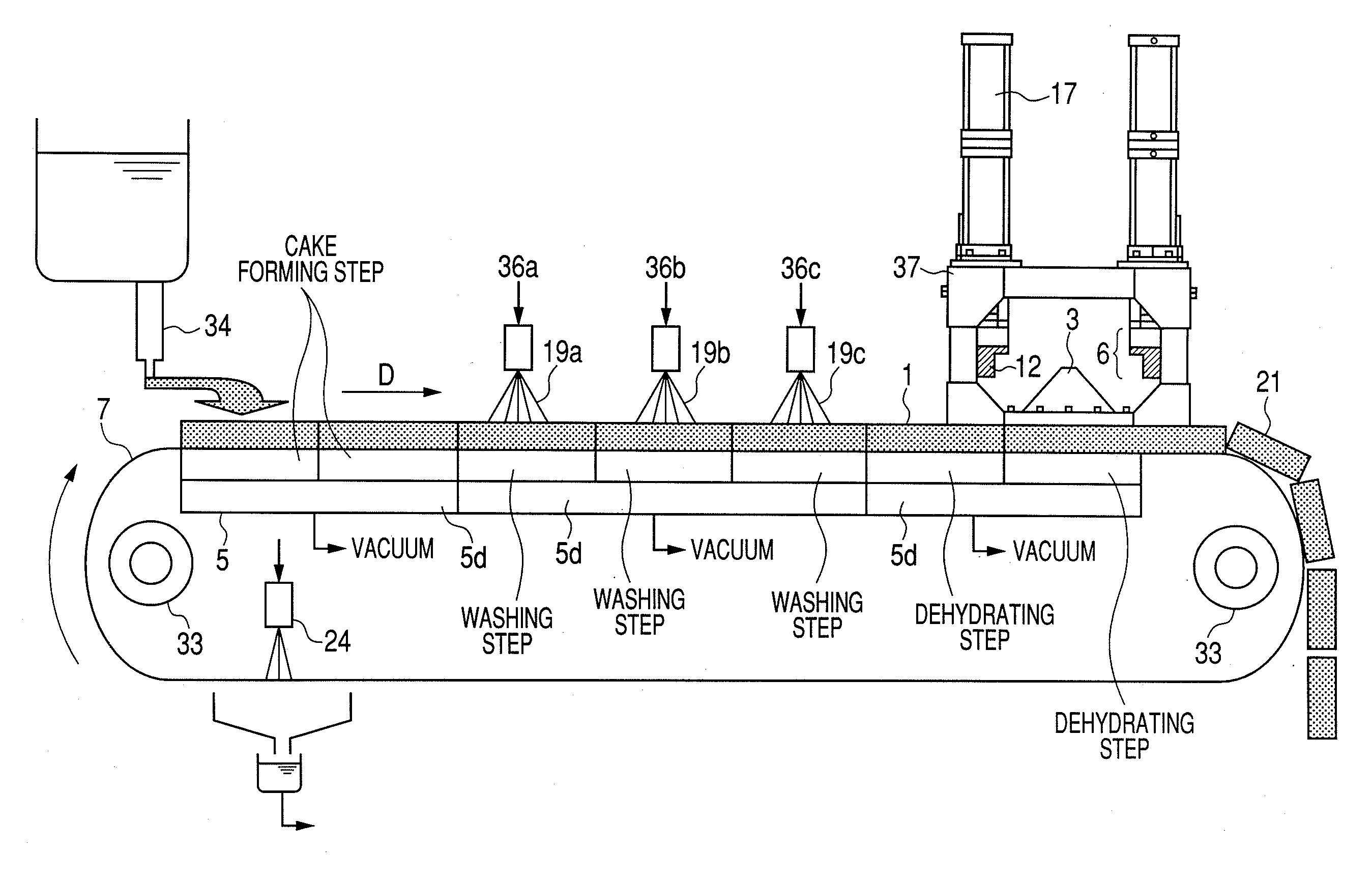
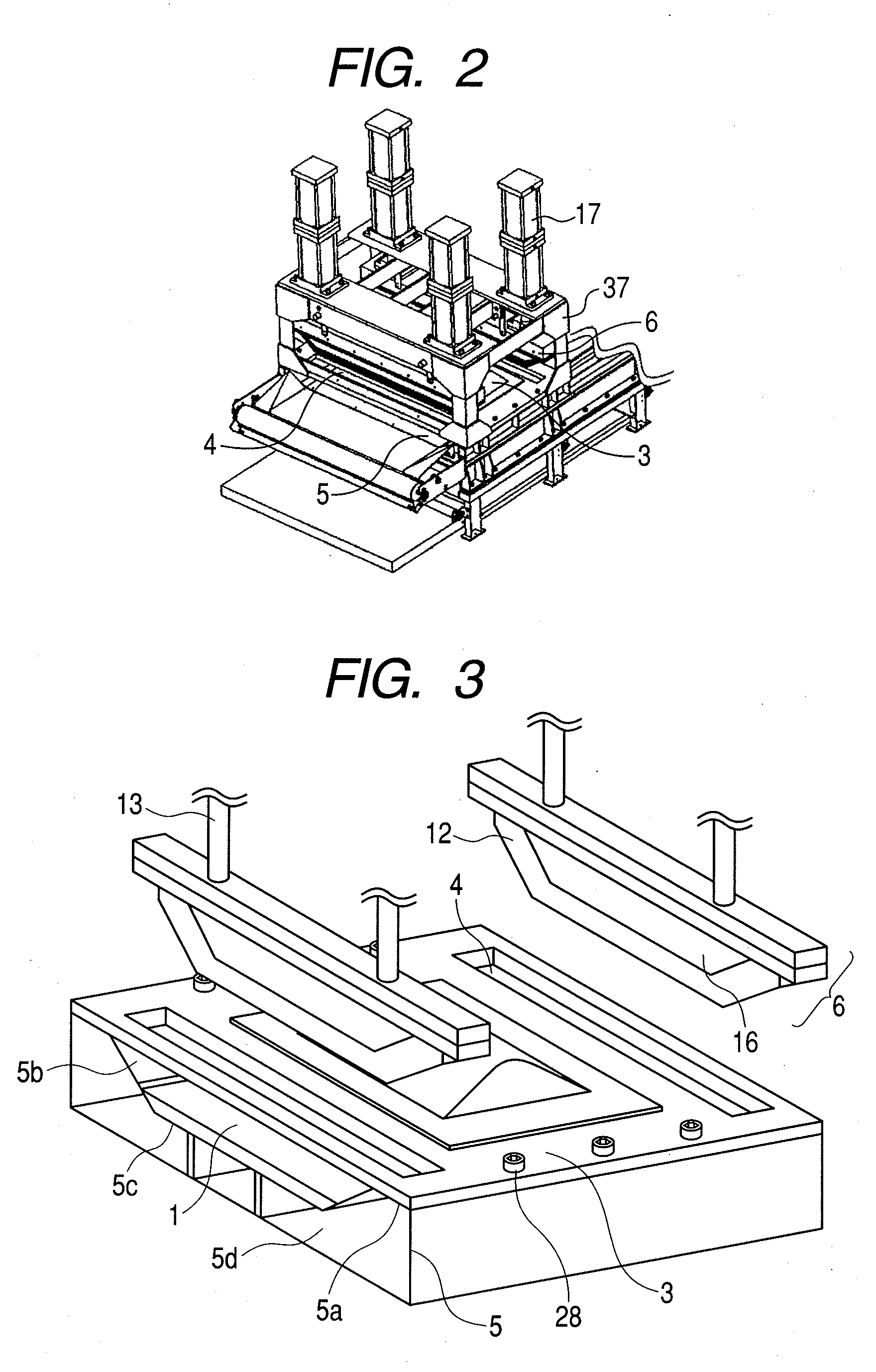
[0018]The present inventors have conducted extensive studies and consequently have found that a water content of a wet toner particle cake can be sufficiently reduced by aerating and dehydrating a cake composed of wet toner particles formed on a belt filter with gas ejected from an aeration unit fixed above a tray while at the same time operating sealing units provided in at least two positions on the upstream and downstream sides of the aeration unit so as efficiently to hermetically seal the aeration air, and thus the present inventors have completed the present invention.
[0019]Besides, the present inventors have found that a load in the drying step, which is a post process, can be reduced and thermal damage to the toner particles can be suppressed by reducing the water content of the wet toner particle cake. Furthermore, the present inventors have found that the toner obtained by the present invention exhibits excellent image characteristics and thus completed the present invention.
[0021]According to the present invention, the water content of the wet toner particle cake can be sufficiently reduced, and thereby the load in a drying step can be alleviated. In addition, less area of the toner particle cake is pressed during sealing operation in comparison with the conventional apparatus, and thereby the deterioration of the toner particles can be alleviated. As a result, the obtained toner can exhibit excellent performance.

Problems solved by technology

When this small sizing of particles is performed, however, dehydration ability deteriorates at the time of separation of toner particles from the dispersion liquid of the toner particles even when the belt filter mentioned above is used, and the water content of the obtained wet toner particle cake tends to increase.
The deterioration in the dehydration ability increases the load in the drying step, which is a post process, and gives thermal damage to the toner particles.
Thus, deterioration in image characteristics such as occurrence of photographic fog is resulted.
However, the above-mentioned apparatus, when applied to a production method of a toner, only presses a plate on a wet toner particle cake, and therefore, there has been such a problem that the wet toner particles are blown out of the press surface where the wet toner particle cake and the plate are closely contacted when the gas is ejected through the perforations.
In addition, since the ejected gas leaks out of the press surface, it becomes difficult to allow the gas to sufficiently pass through the wet toner particle cake.
As a result, there has been such a problem that an increase in the water content remaining in the cake and unevenness of the water content in the cake are caused.
When this method is applied as a toner production method, the water content of wet toner particle cake 1 can be reduced, but dehydration is not sufficient in order to meet the high quality requirement of images demanded in late years.
In addition, the frame-like or annular sealing member, particularly the sealing member which presses a slope surface of the filtration part, is subjected to shear stress and significantly degraded.
Consequently, when continuous operation is performed, the sealing condition of the gas for aeration deteriorates and the dehydration ability deteriorates.
However, dehydration ability was not yet sufficient for meeting the high quality requirement of images demanded in late years and besides the degradation of a sealing member has not been sufficiently suppressed.

Method used


Image

  • Filter cloth traveling type belt filter and production method of toner particles
  • Filter cloth traveling type belt filter and production method of toner particles
  • Filter cloth traveling type belt filter and production method of toner particles

Examples


example 1

[0188]710 parts by mass of ion-exchange water and 850 parts by mass of 0.1 mol / liter Na3PO4 aqueous solution were added, and maintained at 60° C. with stirring at 4800 rpm using Clearmix (manufactured by M Technique). Thereto, 68 parts by mass of 1.0 mol / liter—CaCl2 aqueous solution was gradually added to prepare an aqueous dispersive medium containing a minute water-insoluble dispersion stabilizing agent Ca3 (PO4)2.

[0189]A formulation including

124.0 parts by mass of styrene monomer,

36.0 parts by mass of N-butylacrylate,

13.0 parts by mass of copper phthalocyanine pigment,

40.0 parts by mass of the above-mentioned styrene resin,

10.0 parts by mass of a polyester resin

(Terephthalic acidpropylene oxide modified bispenol A (2 mol adduct)—ethylene oxide modified bispenol A (2 mol adduct) (molar ratio 51:30:20); Acid value 9, glass transition temperature 60° C., Mw=10,000, Mw / Mn=3.20),

0.8 parts by mass of E-88 (manufactured by Orient Chemical Industries, Ltd.), and

15.0 parts by mass of HNP...

example 2

[0222]The dehydrated toner particle cake prepared as in Example 1 was subjected to the dehydration and washing and drying treatments under the same manner as in Example 1 except that the distance K between the lower surface of the gas discharging part and the top surface of horizontal level area of the tray was changed to 400 mm to prepare toner particles. The thickness of the sealing member before compression at the point of time when the dehydration and washing treatment was carried out for consecutive 3 hours was 60.0 mm and the compressibility of the sealing member at the time of the compression was 75%. This dehydrated toner particle cake after the dehydration and washing treatment for 3 hours was disintegrated and the water content was measured and found to be 23%. At the point of time when consecutive 100-hour dehydration and washing treatment was carried out, the thickness of the sealing member before compression was distorted to 42.9 mm. Therefore, the compressibility was 6...

example 3

[0223]The dehydrated toner particle cake prepared as in Example 1 was subjected to the dehydration and washing and drying treatments under the same manner as in Example 1 except that the distance K between the lower surface of the gas discharging part and the top surface of horizontal level area of the tray was changed to 15 mm to prepare toner particles. The thickness of the sealing member before compression at the point of time when the dehydration and washing treatment was performed for consecutive 3 hours was 60.0 mm and the compressibility of the sealing member at the time of the compression was 75%. The dehydrated toner particle cake after this dehydration and washing treatment for 3 hours was disintegrated and the water content was measured and found to be 21%. At the point of time when the consecutive 100-hour dehydration and washing treatment was carried out, the thickness of the sealing member before compression was distorted to 42.9 mm. Therefore, the compressibility was ...


PUM

PropertyMeasurementUnit
thicknessaaaaaaaaaa
thicknessaaaaaaaaaa
water contentaaaaaaaaaa

Abstract

A production apparatus and a production method of toner particles are provided which efficiently and stably reduce the water content of the wet toner particle cake obtained by separating and washing toner particles from toner particle dispersion in a production apparatus of toner particles granulated in a wet process. A wet toner particle cake 1 formed on a belt filter is aerated and dehydrated with air, and at the same time, sealing units provided on the upstream and downstream sides of the aeration unit 3 can be operated to efficiently seal aeration air.

Description

BACKGROUND OF THE INVENTION[0001]1. Field of the Invention[0002]The present invention relates to a filter cloth traveling type belt filter for use in the production of toner particles contained in a toner which is for developing an electrostatic charge latent image in an image forming method such as electrophotography, electrostatic recording method and toner jet method, and a production method of toner particles.[0003]2. Description of the Related Art[0004]Toner particles having a desired particle size are formed in a liquid dispersion medium to obtain a dispersion liquid of toner particles in suspension polymerization method and dissolution suspension method. Then, the toner particles are separated from the dispersion liquid of the toner particles with a separation unit typically represented by a solid-liquid separation apparatus such as a filter apparatus and washed to remove impurities. The cake of the obtained wet toner particles is dried, classified as needed, and then supplem...

Claims


Application Information

Patent Timeline
Patent Type & Authority Applications(United States)
IPC IPC(8): G03G9/08B01D33/70
CPCB01D29/09B01D29/68B01D29/78B01D29/82B01D29/843B01D33/04G03G9/0804G03G9/0815G03G9/0817G03G9/0821
Inventor FUMITA, HIDEKAZUTSUJI, YOSHINORITSUJINO, TAKESHIOMURA, MINORUIKI, SATOSHIAIKO, NAOTO
Owner CANON KK
Learn More