Resin level detection method for ultraviolet curing quick forming process

A molding process and resin liquid technology, applied in liquid level indicators for physical variable measurement, liquid/fluid solid measurement, measuring devices, etc., can solve problems such as inability to measure liquid level signals, weak scattered light intensity, etc., and achieve measurement High resolution, improved quality, and the effect of meeting detection requirements

Inactive Publication Date: 2006-06-21
SUZHOU BC TECH
View PDF0 Cites 27 Cited by
  • Summary
  • Abstract
  • Description
  • Claims
  • Application Information

AI Technical Summary

Problems solved by technology

However, practice has proved that this method cannot measure the liquid level signal

Method used


Image

  • Resin level detection method for ultraviolet curing quick forming process
  • Resin level detection method for ultraviolet curing quick forming process
  • Resin level detection method for ultraviolet curing quick forming process

Examples


Example Embodiment

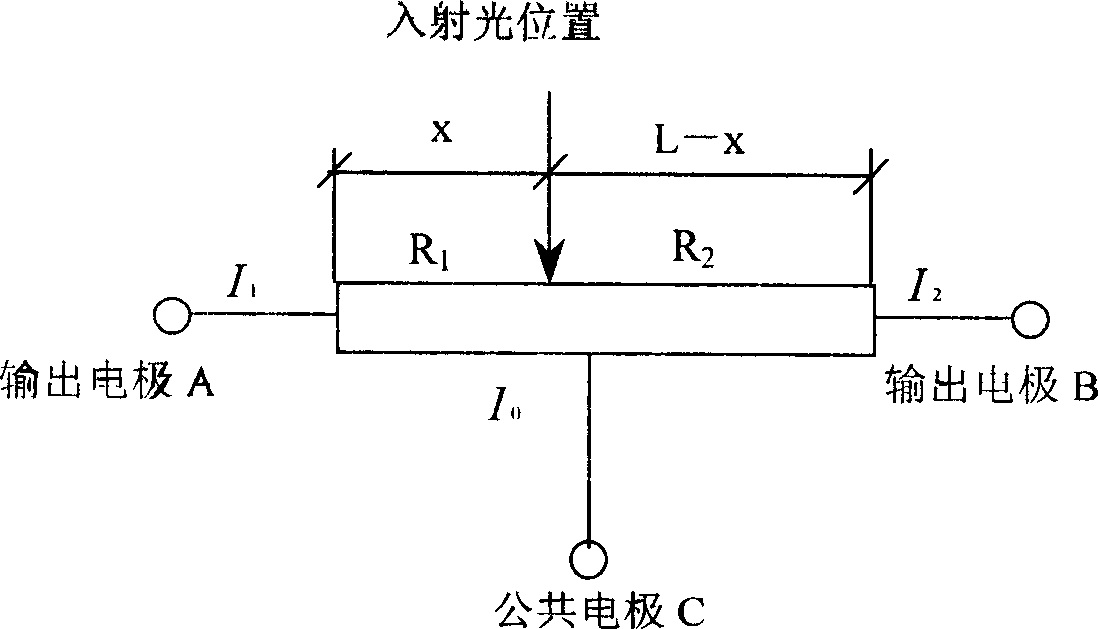
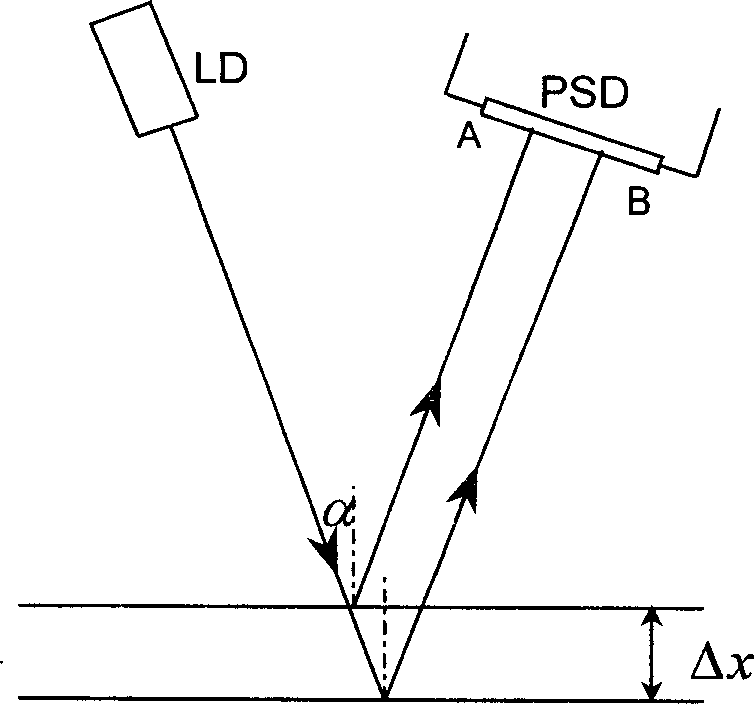
[0017] The resin liquid level detection method used in the light curing rapid prototyping process of the present invention uses the semiconductor light spot position sensor PSD as the sensitive element and the semiconductor laser diode (LD) as the light source, and detects the movement of the resin liquid level based on the principle of reflective tilt angle measurement the amount.

[0018] 1. Basic structure and characteristics of PSD device

[0019] PSD is a semiconductor light spot position sensitive element, its basic structure is as attached figure 1 Shown. When a light beam illuminates a certain point on the photosensitive surface, a certain photo-generated current I will be generated on the photosensitive surface 0 . This current is I 1 And I 2 Respectively flow to the two output electrodes, I 1 And I 2 The shunt relationship depends on the equivalent resistance from the position of the incident light spot to the two poles, and since the P layer impedance of the semiconduc...


PUM


Abstract

The invention discloses a resin liquid-level detecting method of light solidifying rapid patterning technique, which is characterized by the following: setting semiconductor laser device and semiconductor position sensitive device to receive liquid-level reflecting light on the resin groove liquid-level; transmitting the resin liquid level into the electric signal to accomplish the precise measurement of liquid level; adapting high frequency modulation laser to overcome the interference of stray light; changing the laser strength according to the detected liquid level reflectance adaptively; measuring kinds of liquid-level reflectance through closed-loop feedback; adjusting the laser strength according to the proportional integral; making the current I1+I2 equal to constant automatically. The invention overcomes the big error deflect of traditional chip when the reflecting light is weaker, which simplifies the calculation and improves the measuring precision.

Description

technical field [0001] The invention belongs to the technical field of rapid prototyping, in particular to a resin liquid level detection method used in a photocuring rapid prototyping process. Background technique [0002] Light-curing rapid prototyping uses photosensitive resin as a raw material, and the computer controls the scanning trajectory of the ultraviolet laser to make it solidify and form. First, the tank is filled with liquid photosensitive resin, and the ultraviolet laser beam emitted by the laser is scanned point by point on the surface of the photosensitive resin according to the layered section information of the part under the control of the deflection system. The thin layer of resin in the scanned area is irradiated by ultraviolet light. Instead, photopolymerization occurs, curing to form a thin layer of the part. After that, the workbench moves down by a thin layer thickness, so that a new layer of liquid resin is applied on the s...

Claims


Application Information

Patent Timeline
IPC IPC(8): G01F23/292G01F23/22
Inventor 王伊卿卢秉恒丁玉成宗学文李涤尘周宏志施仁张振
Owner SUZHOU BC TECH
Why Eureka
Try Eureka