Strong magnetic impedance magnetic field sensor

A magnetic field sensor and giant magneto-impedance technology, which is applied in the fields of magnetic field-controlled resistors, instruments, measuring magnetic variables, etc., can solve the problems of small structure, low noise, expand the measurement range, etc. Compact and small effect

Inactive Publication Date: 2006-06-28
ZHUHAI COLLEGE OF JILIN UNIV
View PDF0 Cites 18 Cited by
  • Summary
  • Abstract
  • Description
  • Claims
  • Application Information

AI Technical Summary

Problems solved by technology

[0008] The magnetic field sensor designed by the present invention is based on the giant magneto-impedance (GMI) effect of the amorphous soft magnetic strip, which solves the problems of one-to-one correspondence betwe...

Method used


Image

  • Strong magnetic impedance magnetic field sensor
  • Strong magnetic impedance magnetic field sensor
  • Strong magnetic impedance magnetic field sensor

Examples


Embodiment 1

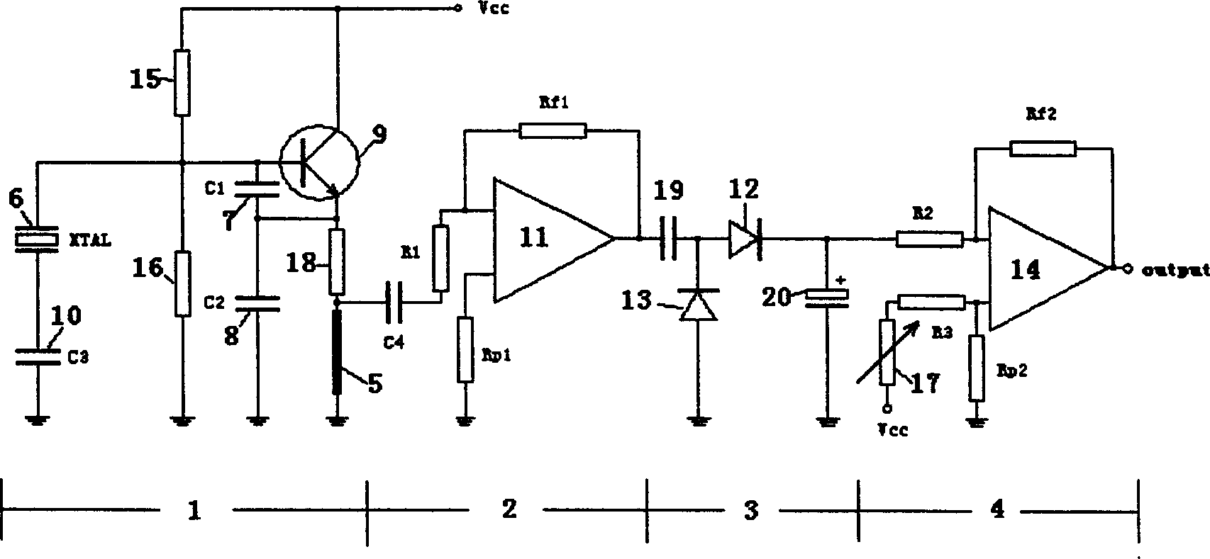
[0021] figure 2 Among them, 1 is the Colpitts oscillator circuit, 2 is the preamplifier, 3 is the rectifier circuit, 4 is the zero-adjustment output amplifier, 5 is the amorphous band, 6 is the crystal oscillator, and 7 is the feedback capacitor C 1 , 8 is the feedback capacitor C 2 , 9 is the transistor, 10 is the starting capacitor C 3 , 11 is a high-frequency operational amplifier, 12 is two rectifier diodes, 14 is an operational amplifier, 16 is two voltage divider resistors with equal resistance, 17 is a variable resistor, 18 is an emitter current limiting resistor, and 19 is a filter capacitor , 20 is the voltage stabilizing capacitor.

[0022] Corbitz oscillator circuit 1 supply voltage V cc It can be 12V, and the design of stabilizing the static operating point of the transistor 9 base is adopted. Since the resistance values ​​of the two voltage dividing resistors 16 are equal, the static operating voltage of the transistor 9 base is 6V, and the static operating vo...

Embodiment 2

[0026] An embodiment of the data of each part of the circuit element is given.

[0027] figure 2 In the Corbitz oscillating circuit 1, the amorphous strip 5 is 10um to 40um in thickness, 1mm to 2mm in width, and 60mm to 200mm in length. It has a giant magneto-impedance (GMI) effect, and its sensitivity is greater than 1% / Oe. Co 72 Zr 8 B 20 Amorphous strip; Transistor 9 uses a high-frequency transistor of the 2SC1815 model, and its cut-off frequency f r 5 times higher than the frequency of the crystal oscillator 6. The frequency of the crystal oscillator 6 is above 1MHz, and the starting capacitor C 3 15pF ~ 10nF can start to vibrate. The two voltage dividing resistors 16 can be selected as 10kΩ; the emitter current limiting resistor 18 is 390Ω; the feedback capacitor C 1 1000pF~2200pF, feedback capacitance C 2 60pF~200pF, and the feedback capacitance C 1with feedback capacitor C 2 The ratio is between 2 and 25. The oscillating frequency of the Corbitz oscillating c...


PUM


Abstract

A transducer of giant magnetic impedance field is prepared as applying transistor with cut ¿C off frequency of 3 ¿C 60 MH2 as kerr magnetic oscillation circuit, applying the same resistance value on two voltage ¿C dividing resistances between base electrode and ground as well as between base electrode and DC power supply, series ¿C connecting crystal oscillator with frequency of 1¿C 20 MH2 with vibration starting capacity between base electrode and ground, existing noncrystalling belt as part of radio electrode load.

Description

technical field [0001] The invention belongs to the technical field of weak magnetic field measuring devices, in particular to a giant magneto-impedance (GMI) magnetic field measuring sensor. Background technique [0002] Magnetic field measurement is an important issue in various fields of production and scientific research. Now many new technologies and materials are applied to magnetic field measurement devices. The most commonly used magnetic field sensors include Hall (Hell) sensors, fluxgate sensors, vibrating or rotating coils, etc., but these sensors have certain defects. The output signal of the Hall device changes little, and there is a certain anisotropy of the magnetic field direction when measuring the magnetic field, which is suitable for the measurement of medium and strong magnetic fields; the fluxgate and the detection coil measure the magnetic field, and the winding of the coil is particularly accurate, and the signal processing requirements are relatively ...

Claims


Application Information

Patent Timeline
IPC IPC(8): G01R33/09H01L43/08
Inventor 张涛韩冰李明任欢汤新岩
Owner ZHUHAI COLLEGE OF JILIN UNIV
Why Eureka
Try Eureka