Cut processing method, cut processing apparatus and work-piece supporting construction used with said apparatus

A technology for cutting processing and workpieces, which is applied in the direction of shearing devices, metal processing, metal processing equipment, etc., and can solve the problems of improving cutting accuracy, not being able to cut with high precision, and gaps in workpiece clamping thickness.

Active Publication Date: 2006-07-05
UHT CORP
View PDF2 Cites 10 Cited by
  • Summary
  • Abstract
  • Description
  • Claims
  • Application Information

AI Technical Summary

Problems solved by technology

[0005] However, generally, the workpiece is temporarily clamped with tape or the like while the peripheral edge of the rectangular frame-shaped workpiece holder is attached to the upper surface, so a gap of approximately the thickness of the workpiece clamping is formed between the table surface and the lower stripper plate, which become the reference plane of the cutting machine.
[0006] Patent Document 2 Therefore, in the cutting process of Patent Document 2, although it is small, the tip of the upper cutting edge presses down on the workpiece through the above-mentioned slit to perform full cutting, so there is a problem that it cannot be cut with high precision at a predetermined pitch.
[0007] In addition, in Patent Document 3, although the upper and lower cutting edges cut simultaneously, since the lower stripper plate is arranged on the back surface of the workpiece between the cutting line, the workpiece is stretched and half-cut while being pushed down. Improvement in cutting accuracy at a predetermined pitch cannot be expected

Method used


Image

  • Cut processing method, cut processing apparatus and work-piece supporting construction used with said apparatus
  • Cut processing method, cut processing apparatus and work-piece supporting construction used with said apparatus
  • Cut processing method, cut processing apparatus and work-piece supporting construction used with said apparatus

Examples


Embodiment 1

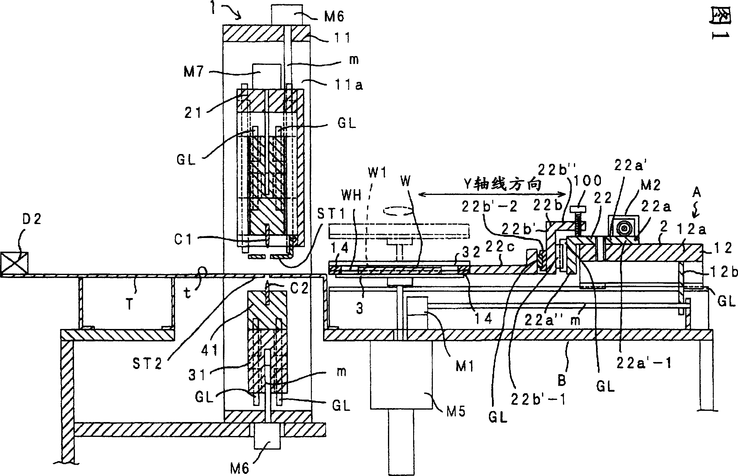
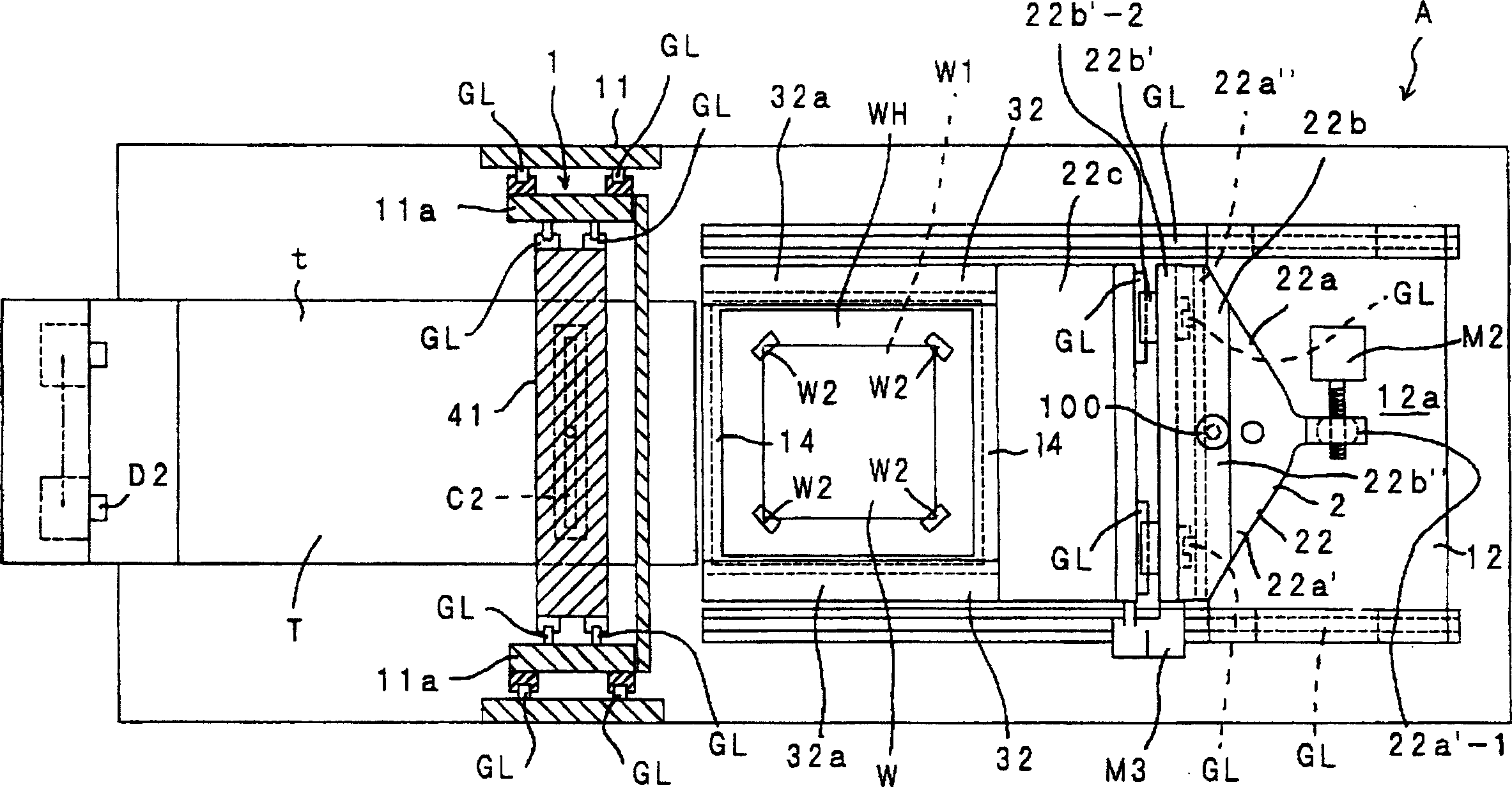
[0089] Cutting processing device A is, as shown in Figure 1, figure 2 , Figure 4 , Figure 5 As shown, on the front side of the Y-axis direction of the support table B, a cutting machine 1 and a table T with the table t as the reference plane will be installed, and the moving device 2 that can release the clamping workpiece W will be placed on the support table B in the YX-axis direction. The control is operable and set so that it can be corrected in the θ direction, and the indexing table is set at the standby position of the moving device 2 .

[0090] Above-mentioned support platform B is, as shown in Figure 1~ image 3 As mentioned above, the guide rail GL arranged parallel to the direction of the cutting machine is used to make the moving device 2 move controllably in the direction of the Y axis.

[0091] The above-mentioned mobile device 2 is, for example, figure 2 , image 3 As shown, the door-shaped body 12 slidably engaged on the above-mentioned guide rail GL and...

Embodiment 2

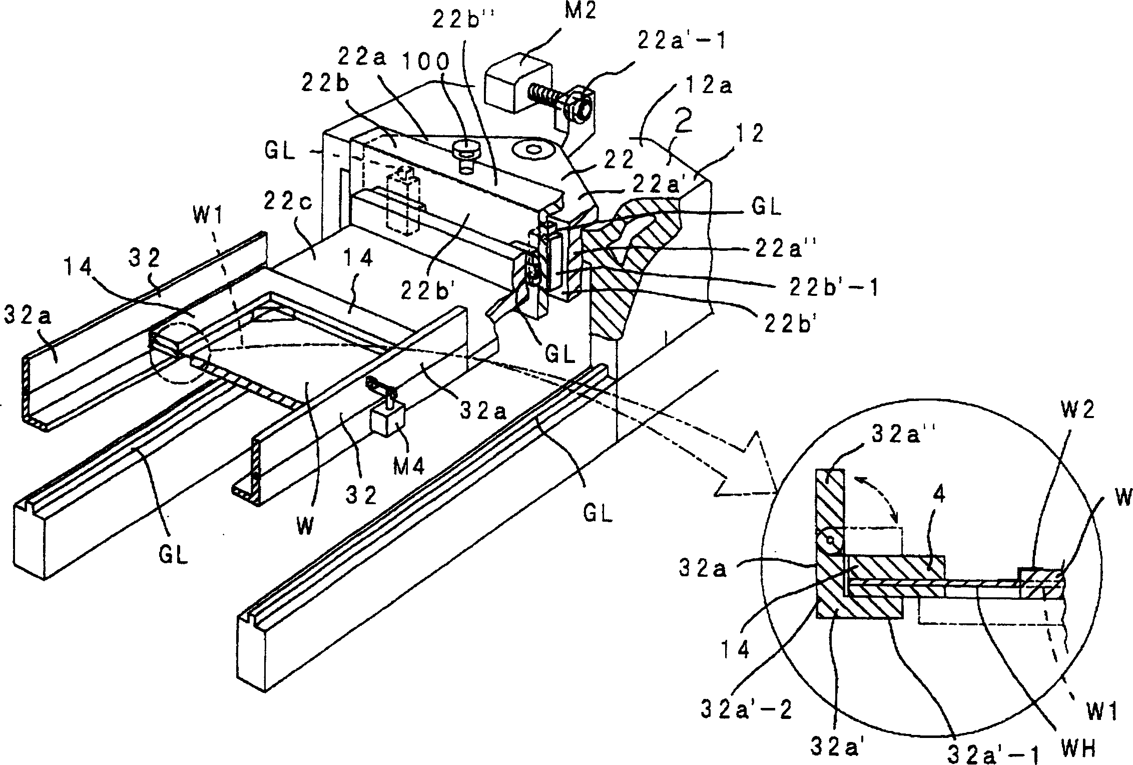
[0126] Second, according to Figure 9 A second embodiment of the cutting device for performing the cutting method will be described. The clamper 32 of this embodiment is capable of releasing the clamping of the frame body 14 front and rear in the Y-axis direction by the edge member 14 .

[0127] The holder 32, in detail, on the above-mentioned fastener supporting body 22c, forms the parallel constituent pieces 32b' in the respective Y-axis directions into a flat plate shape, and forms the constituent pieces 32b' connecting the two ends of the constituent pieces 32b' into an L shape. The rectangular frame 32b of the rectangular frame 32b is arranged continuously toward the direction of the cutting machine, and the side on which the rotating body 32a is pivoted on the front and rear forming pieces 32b' corresponds to the horizontal section 32b"-1 of the forming piece 32b', and the horizontal piece part 32 is accommodated. The concave part 14a of "-1 lies in the above-mentioned f...

Embodiment 3

[0131] Second, according to Figure 10 A third embodiment of a cutting device for carrying out a cutting method will be described, and this embodiment shows a modified example of the workpiece support structure.

[0132] In this embodiment, the workpiece holding plate WH is made of a synthetic resin material that allows elastic deformation.

[0133] As such, when the workpiece clamping plate WH is made of a synthetic resin material that allows elastic deformation, even if the back of the workpiece W is not in full-width sliding contact with the table t due to the elastic deformation function, the workpiece W can be elastically deformed by its own weight. It can be slidably contacted with the table surface t, and the mounting position of the workpiece WH to the workpiece W by the workpiece clamping plate WH does not require high precision.


PUM


Abstract

To provide a cutting method and a cutting device for improving cutting accuracy by preventing deformation by preventing the push-down of a workpiece by an upper cutting blade at the time of cutting (full cut or half cut) of the upper cutting blade. The workpiece W inserted into a hole W1 opened in a sheet WH for a thin work holder is temporarily fastened to the sheet WH for the work holder by being located in a middle region of the thickness of the workpiece W not to be in contact with the upper and lower cutting blades C1 and C2 for the half cut. The workpiece W is half-cut by being shared over the whole width without cutting the sheet WH for the work holder by the upper and lower cutting blades C1 and C2 of required lengths which are longer than the whole width of the workpiece W and shorter than the sheet WH for the work holder. The push-down of the workpiece W by the upper cutting blade C1 at the time of the half-cut is prevented by a lower stripper ST2 fixedly provided in the table surface height of cutting machine 1. The push-up of the workpiece W by the lower cutting blade C2 is prevented by an upper stripper ST1.

Description

technical field [0001] The present invention relates to a method for cutting and processing workpieces (such as wiring substrates, packaging substrates, laminated substrates of capacitors, inductors, resistors, magnetic materials, etc., and laminated electronic components), a cutting processing device, and a cutting device used for the cutting. The workpiece support structure of the processing device. Background technique [0002] In the past, the cutting-off processing device sucks the workpiece through the vacuum-type indexing table, and cuts the workpiece at a predetermined interval with a cutting-off processing machine equipped with an upper cutting blade every time it rotates 90 degrees, and forms the workpiece in a sheet shape (for example, refer to Patent Document 1 ). [0003] In this patent document 1, since the workpiece has flexibility, it is troublesome to handle, so the workpiece is temporarily clamped with an adhesive such as adhesive tape on a metal rectangul...

Claims


Application Information

Patent Timeline
Patent Type & Authority Applications(China)
IPC IPC(8): B26D1/10B26D1/11B26D7/01B26D7/27B26D7/08B26D7/18B26D7/26B26D7/10B26D5/00
CPCB23D15/02B23D15/12B23D33/08
Inventor 福岛正人田中寿良山田俊辅北原广之
Owner UHT CORP
Why Eureka
Try Eureka