Collection device for cold water solidification heat
A collection device and solidification heat technology, applied in the direction of heating devices, other non-combustion heat generation, heating fuel, etc., can solve the problems of immature frozen ice heat exchange technology, lack of effective collection means of cold water solidification heat, etc., and achieve huge Energy saving and environmental protection benefits, simple structure, high heat extraction efficiency
- Summary
- Abstract
- Description
- Claims
- Application Information
AI Technical Summary
Problems solved by technology
Method used
Image

Examples
specific Embodiment approach 1
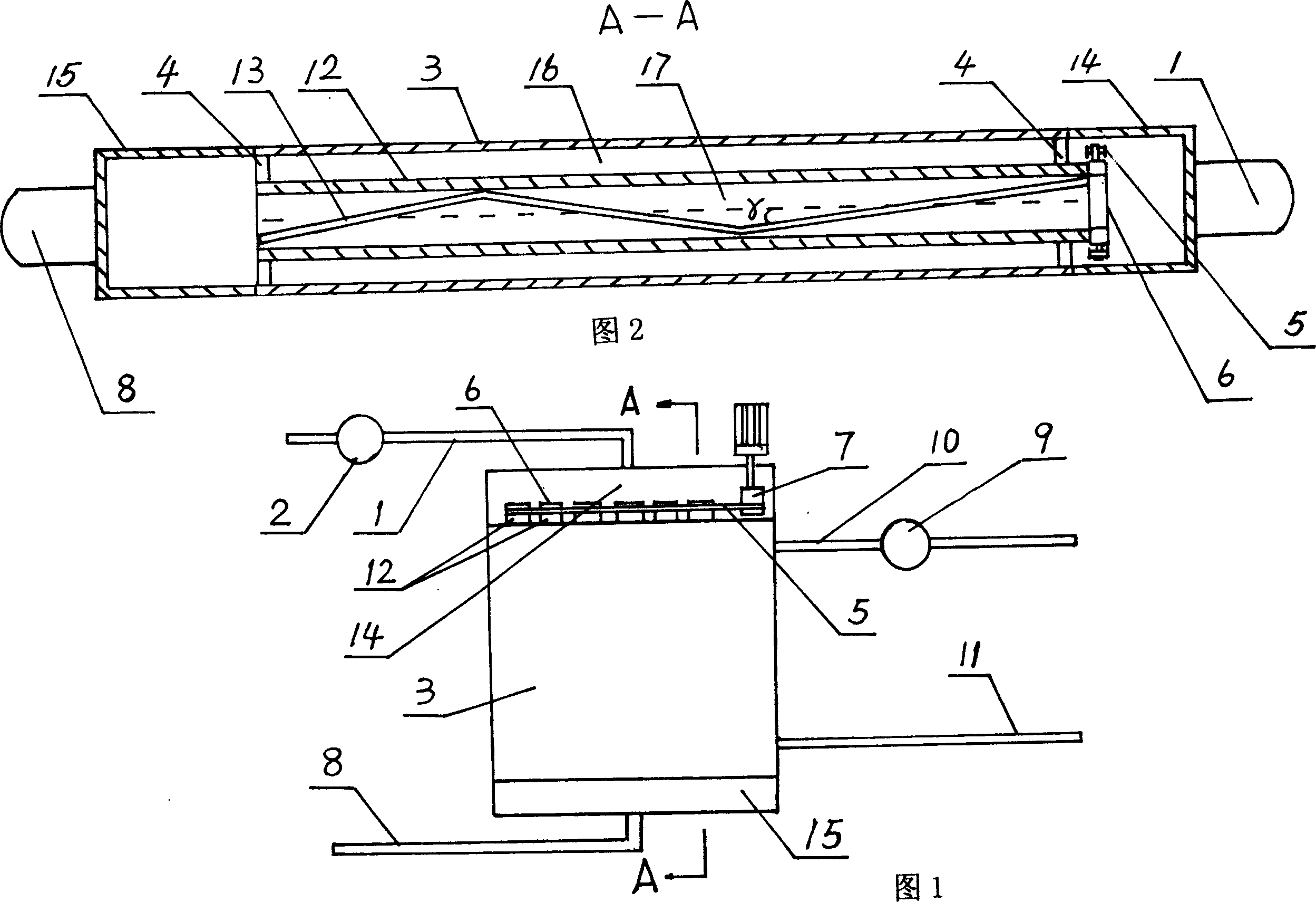
[0006] Specific embodiment one: (referring to Fig. 1, Fig. 2) this embodiment consists of a water intake pipe 1, a cold water pump 2, a heat exchange freezer 3, a sealing ring 4, a chain 5, a main shaft 6, a motor reducer 7, and a drain pipe 8 , circulating pump 9, circulating water outlet pipe 10, circulating water inlet pipe 11, heat exchange freezing pipe 12, auger scraper 13, cold water inlet mask 14 and ice floc outlet mask 15; cold water inlet mask 14 and ice floc outlet mask 15 respectively fixed on the two ends of the heat exchange freezer 3, the outlet end of the water intake pipe 1 communicates with the cold water inlet mouthpiece 14, the inlet end of the water intake pipe 1 communicates with the outlet end of the cold water pump 2, and the inlet end of the cold water pump 2 It is connected with the water source, the inlet end of the drain pipe 8 is connected with the ice floc outlet mouthpiece 15, the outlet end of the drain pipe 8 is connected with the water source,...
specific Embodiment approach 2
[0007] Embodiment 2: (see FIG. 1 and FIG. 2 ) The inner diameter of the heat exchange and freezing tube 12 of this embodiment is 60-100 mm. The length of the heat exchange and freezing pipe 12 is 5-8m. The number of roots is determined by the required heat exchange and freezing area. Many heat exchange freezing tubes 12 are arranged in several rows in parallel, 5-8 in every row. Other compositions and connections are the same as in the first embodiment.
specific Embodiment approach 3
[0008] Specific embodiment three: (see Fig. 1, Fig. 2) the oblique angle γ of the auger scraper 13 of this embodiment deviates from the axial direction by 20 degrees, and the outer diameter of the auger scraper 13 is smaller than the inner diameter of the heat exchange and freezing tube 12 0.5-1mm. Other compositions and connections are the same as in the first embodiment. Through the slow rotation (1 revolution per minute) of the auger scraper 13, the ice formed on the inner wall of the heat exchange and freezing tube is scraped and cut off, and flows away with the water, so as to ensure the non-blocking operation of the subsequent pipeline.
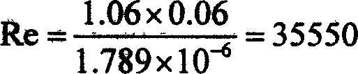
[0009] The design calculation of the above embodiment
[0010] Axial flow velocity in the pipe: υ=1m / s
[0011] Tube inner diameter: d=0.06m
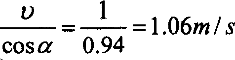
[0012] Scouring speed of wall surface after adding spiral: (α is the rotation angle, α=20°)
[0013] υ cos α ...
PUM
 Abstract
Description
Claims
Application Information
PatSnap Eureka turns technology decisions into work you can execute. Powered by our Innovation Knowledge Graph, it runs expert workflows across engineering, life sciences, materials and intellectual property. Get your review-ready output in minutes.


