Process gas afterheat recovery device of coking carbonization chamber furnace top and heat-removing element

A waste heat recovery device and process gas technology, applied in coke oven heating, coke oven, dry distillation gas discharge device, etc., can solve the problems that waste heat recovery cannot be conveniently and effectively applied, and improve comprehensive energy utilization efficiency and heat extraction efficiency High, improve the effect of safety and reliability

Active Publication Date: 2012-07-04
NANJING SHENGNUO HEAT PIPE
View PDF1 Cites 0 Cited by
  • Summary
  • Abstract
  • Description
  • Claims
  • Application Information

AI Technical Summary

Problems solved by technology

However, as mentioned above, none of the existing heat extraction elements and heat extraction devices can be conveniently and effectively applied to the waste heat recovery of the process gas in the coking chamber.

Method used


Image

  • Process gas afterheat recovery device of coking carbonization chamber furnace top and heat-removing element
  • Process gas afterheat recovery device of coking carbonization chamber furnace top and heat-removing element
  • Process gas afterheat recovery device of coking carbonization chamber furnace top and heat-removing element

Examples


Embodiment 1

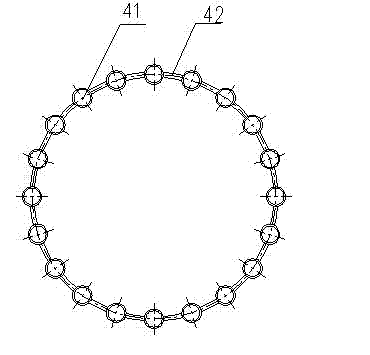
[0033] Such as figure 1 As shown, when the outer tube diameter d of the heat pipe 41 is less than or equal to 25mm, and the central arc length of two adjacent heat pipes is less than or equal to 2d, the circumferential ring fins are used, that is, the ring fins 42 are placed between the heat pipes 41. The annular line formed by the center of the tube is connected with each heat pipe 41 .

Embodiment 2

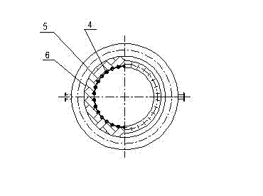
[0035] Such as figure 2 As shown, when the outer diameter d of the heat pipe 41>25mm, and the central arc length of two adjacent heat pipes is less than or equal to 2d, the circumferential cut tube fins are used, that is: the annular fins 42 and each The heat pipes 41 are tangential to each other in the circumferential direction, and the inner peripheral surface of the annular fin 42 coincides with the inner peripheral surface formed by each heat pipe 41 .

Embodiment 3

[0037] Such as image 3 As shown, the annular circumferential tube-fin screen adopts a circumferential tube-fin screen with an inner cylinder, that is, the annular fin screen 42 is connected with each heat pipe 41 on its outer circumferential surface. The annular fin screen 42 becomes the inner cylinder of the circumferential tube fin screen.

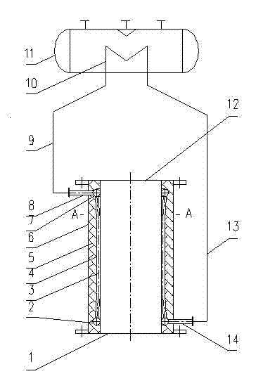
[0038] Such as Figure 4 , Figure 5 As shown, the waste heat recovery device for process gas at the top of the coking chamber of the present invention includes an annular circumferential tube-fin screen 4, an upper collection coil 7, a lower collection coil 2, a heat release pipe 10, and a steam drum 11. A process gas outlet 12 and a process gas inlet 1 are respectively provided at the upper and lower ports of the tube-fin screen 4, and the process gas inlet 1 is connected to the top of the coking chamber furnace; wherein, the lower ends of the heat pipes of the annular circumferential tube-fin screen 4 pass through The lower collec...


PUM

PropertyMeasurementUnit
diameteraaaaaaaaaa
diameteraaaaaaaaaa
boiling pointaaaaaaaaaa

Abstract

The invention provides a process gas afterheat recovery device of a coking carbonization chamber furnace top and a heat-removing element. The heat-removing element comprises a plurality of heat pipes, wherein the heat pipes are filled with a working solution, annularly arranged and connected by an annular fin screen to form an annular peripheral pipe fin screen; the afterheat recovery device comprises the annular peripheral pipe fin screen arranged on the coking carbonization chamber furnace top and a steam pocket; a process air inlet and a process air outlet are respectively arranged at the upper end and the lower end of the annular peripheral pipe fin screen, and the process air inlet is abutted with the process air outlet on the coking carbonization chamber furnace top; the upper end and the lower end of each heat pipe of the annular peripheral pipe fin screen are respectively communicated with an upper collection coil and a lower collection coil; and the upper collection coil and the lower collection coil are respectively connected with heat-releasing pipes placed in the steam pocket through pipelines to form a sealed circulation loop of the work solution in each heat pipe of the annular peripheral pipe fin screen. In the invention, a great deal of process gas afterheat of the coking furnace top, which has high temperature and is rich in recyclable substances and discharged from the top of the carbonization chamber, can be effectively recycled, and the temperature is reduced from 800 DEG C to over 450 DEG C at the coking point, thereby the invention is safe and environment-friendly, saves energy, and is benefit for greatly reducing operating cost and expenses.

Description

technical field [0001] The invention relates to a heat exchanging element, in particular to a heat-taking element including a heat pipe. [0002] The present invention also relates to a waste heat recovery device for recovering the waste heat of the process gas at the top of the coking chamber composed of the above-mentioned heat-taking elements. Background technique [0003] At present, most of the coking process adopts the traditional process. During the process, the high-temperature process gas generated by pyrolysis is discharged from the top of each carbonization chamber. The process gas cools down, and then enters the next process. For example, a horizontal tube primary cooler for cooling coke oven gas disclosed in 200710051923. The lower section of the spray pipe is provided with a broken tray above the lower section of the spray pipe to control the condensate and spray liquid in the upper section of the primary cooler to be directly drawn out without passing through...

Claims


Application Information

Patent Timeline
Patent Type & Authority Patents(China)
IPC IPC(8): F28D15/02F28F1/12F22B1/18C10B27/00
CPCF28D15/0266Y02P20/129
Inventor 杨峻段鸾芳王明军刘兴孙立宇李来所
Owner NANJING SHENGNUO HEAT PIPE
Why Eureka
Try Eureka