CO2 corrosion-prevented cement system for oil well

A technology of carbon dioxide and cement, which is applied in the field of cement system, can solve the problems of less research on corroded cement sheath, shorten the production life of oil and gas wells, and not pay enough attention to it, and achieve the effects of enhanced compactness, high corrosion resistance, and slowed down corrosion rate

Inactive Publication Date: 2006-07-19
DAQING PETROLEUM ADMINISTRATION
View PDF2 Cites 6 Cited by
  • Summary
  • Abstract
  • Description
  • Claims
  • Application Information

AI Technical Summary

Problems solved by technology

Thereby shortening the production life of oil and gas wells and causing huge economic losses
[0003] Currently, although CO 2 The corrosion of downhole pipes has attracted the attention of various domestic oil fields, and corresponding anti-corrosion research has been carried out, but the attention is still not enough, especially for CO

Method used


Image

  • CO2 corrosion-prevented cement system for oil well
  • CO2 corrosion-prevented cement system for oil well
  • CO2 corrosion-prevented cement system for oil well

Examples


Embodiment Construction

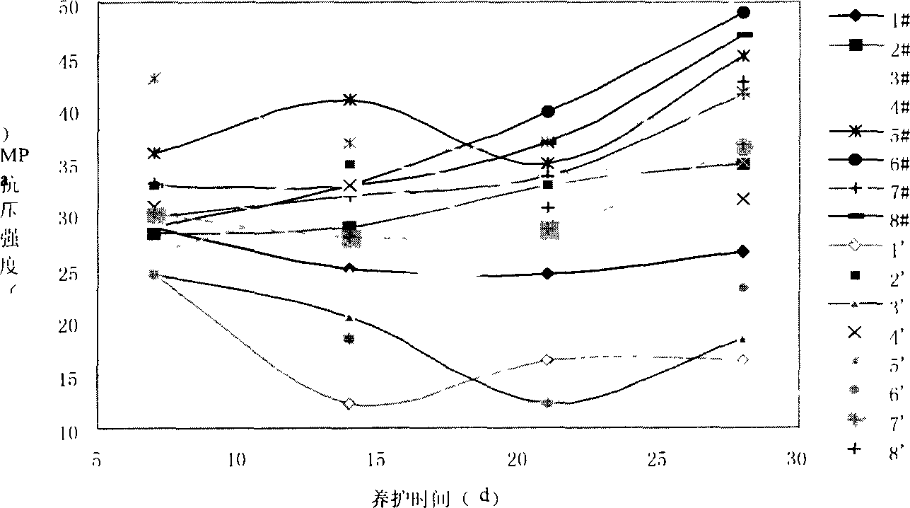
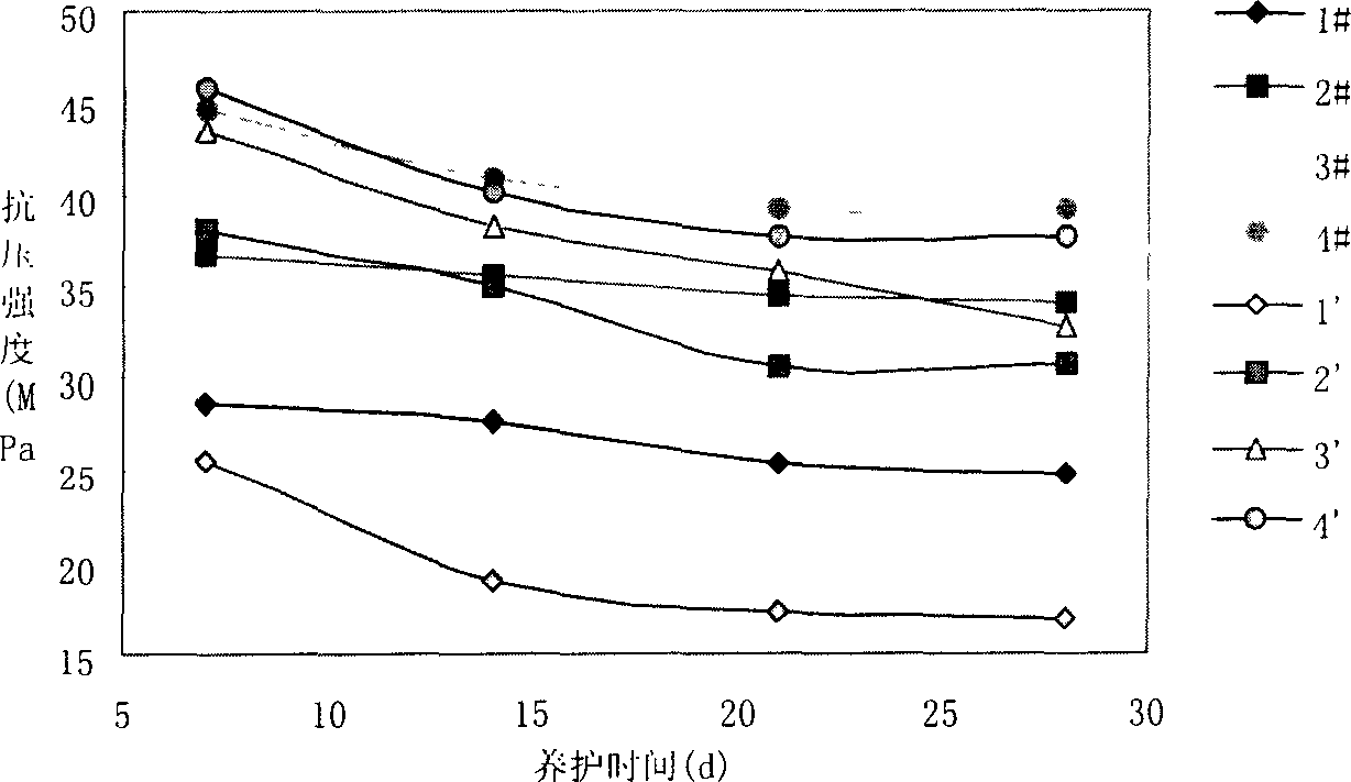
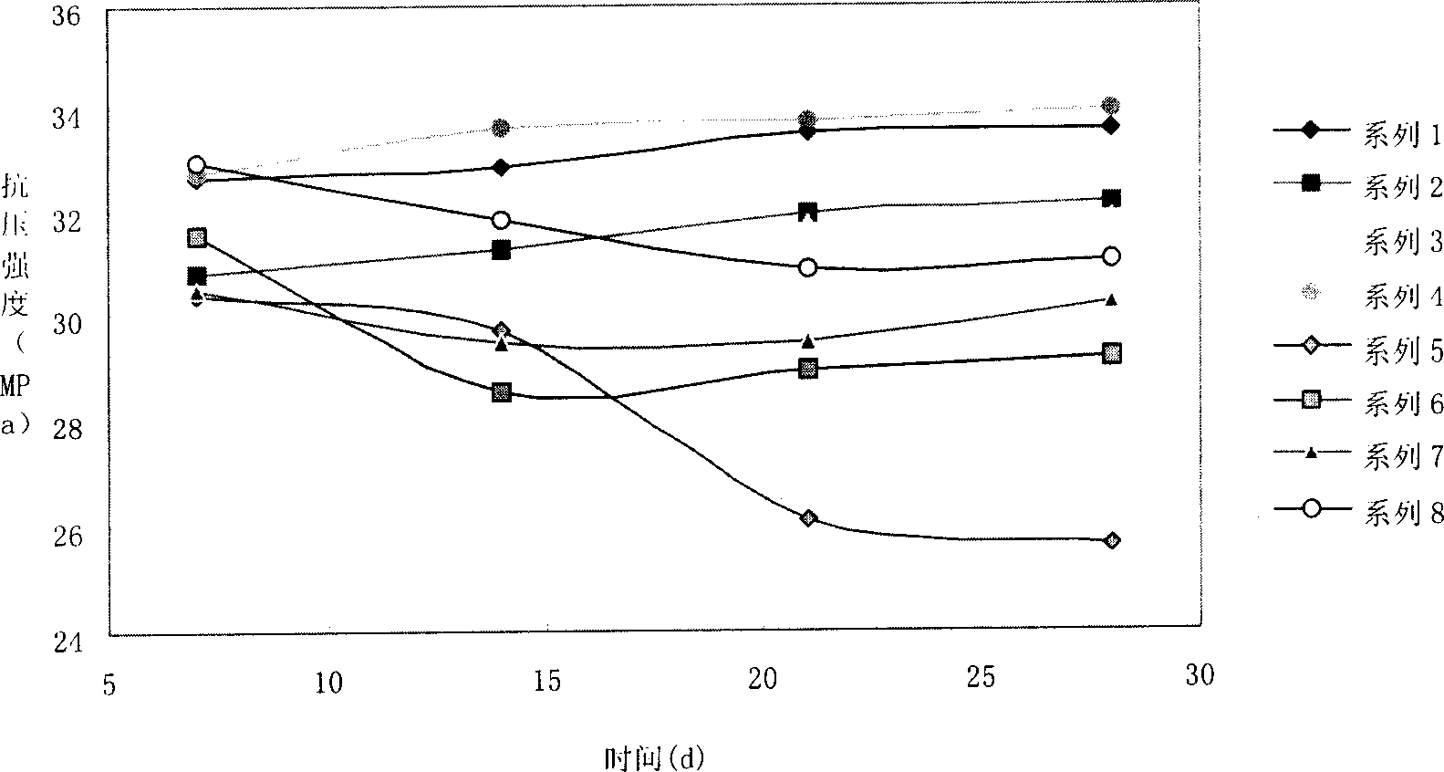
[0037] Further description will be given below in conjunction with specific examples. The cement system for preventing carbon dioxide corrosion for oil wells includes the following components: the following components are proportioned by mass percentage based on the total weight of cement: 8-35% silica sand or quartz Sand, 3-5% silica, 6.5-18% fluid loss reducer DSJ, DSHJ or DHL, cement. Wherein DSJ is made of 75% N,N-dimethylacrylamide, 5% sodium propylene sulfonate, 20% N-vinylpyrrolidone; DHL is the fluid loss reducer described in the application document No. 03101262.0 (the molecular weight of styrene-butadiene latex is 5000-50000, styrene-butadiene latex is a random polymerization of styrene and butadiene, and the values ​​of x, y and z are 1000-1500); DSHJ is in the application document with application number 02157940.7 The fluid loss reducer and microsilica are represented by DCR.


PUM


Abstract

The invention relates to a cement system for preventing carbon dioxide corrosion in oil wells, which comprises the following constituents (by mass percent): 8-35% of quartz sand or ganister sand, 5-8% of micro silicon powder, 6.5-18% of filtrate loss reduction additive DSJ, DSHJ or DHL, and cement.

Description

Technical field: [0001] The invention relates to a cement system used in the field of oil field drilling, in particular to a cement system used in oil wells to prevent carbon dioxide corrosion. Background technique: [0002] Carbon dioxide often exists in oil and gas as a component of natural gas or petroleum-associated gas. 2 Enhanced oil recovery technology will also reduce CO 2 into the underground environment. CO 2 It is extremely corrosive to steel when dissolved in water. Under suitable humidity (relative humidity greater than 30%) and pressure environment conditions in the downhole CO 2 It will cause rapid general corrosion and severe local corrosion of casing steel, which will cause early corrosion failure of pipelines and equipment, and even cause corrosion fracture of production oil casing. At the same time CO 2 It will also corrode the oil well cement, reduce the alkalinity of the cement stone, reduce the strength of the cement sheath and increase the permea...

Claims


Application Information

Patent Timeline
IPC IPC(8): C04B28/00C04B14/06C04B24/00C04B103/46C04B111/22
Inventor 徐明弓玉杰肖志兴王广雷高莉莉和传健徐永辉
Owner DAQING PETROLEUM ADMINISTRATION
Why Eureka
Try Eureka