Ultrasonic time-of-flight diffraction detection method based on synthetic aperture focusing technique

A technology for synthetic aperture focusing and detection methods, applied in the use of sound waves/ultrasonic waves/infrasonic waves to analyze solids, special data processing applications, instruments, etc., and can solve problems such as inability to accurately locate and quantify plates

Inactive Publication Date: 2006-07-19
HARBIN INST OF TECH
View PDF0 Cites 26 Cited by
  • Summary
  • Abstract
  • Description
  • Claims
  • Application Information

AI Technical Summary

Problems solved by technology

[0003] In order to overcome the problem that the ultrasonic transit time method in the prior art cannot accurately locate and quantify the defects in the plates and their structural welds, the present inventi

Method used


Image

  • Ultrasonic time-of-flight diffraction detection method based on synthetic aperture focusing technique
  • Ultrasonic time-of-flight diffraction detection method based on synthetic aperture focusing technique
  • Ultrasonic time-of-flight diffraction detection method based on synthetic aperture focusing technique

Examples


specific Embodiment approach 1

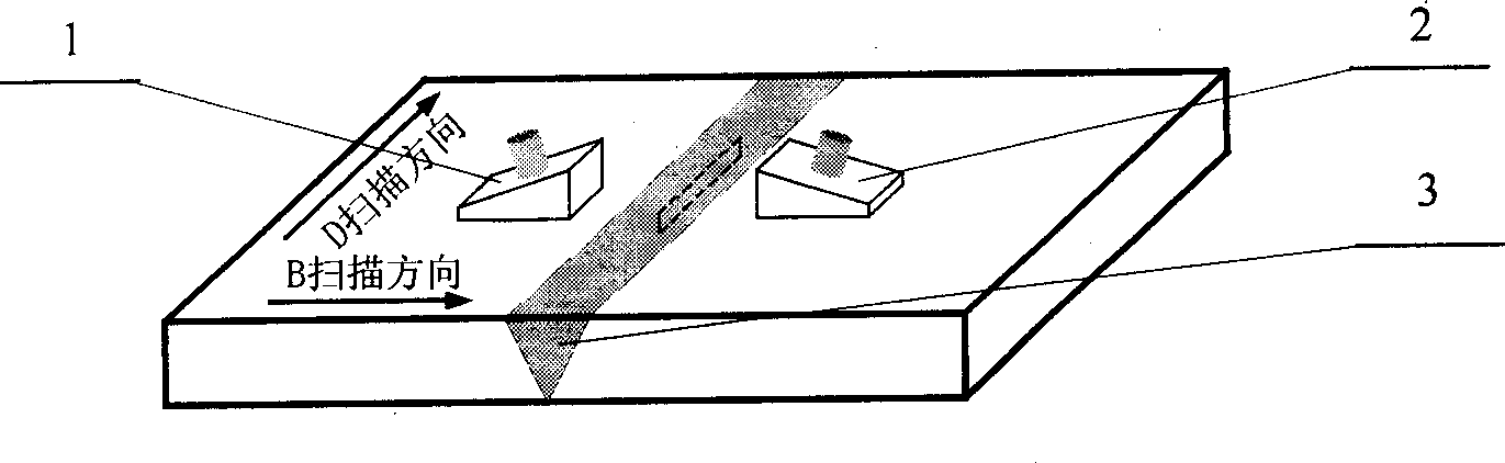
[0030] Specific implementation mode one: see Figure 1 to Figure 8 In this specific embodiment, the detection method of the present invention is described by taking internal buried defects as an example. This specific embodiment is to detect the internal buried defects processed on the aluminum alloy plate with a thickness of 20mm, and the detection steps are as follows:

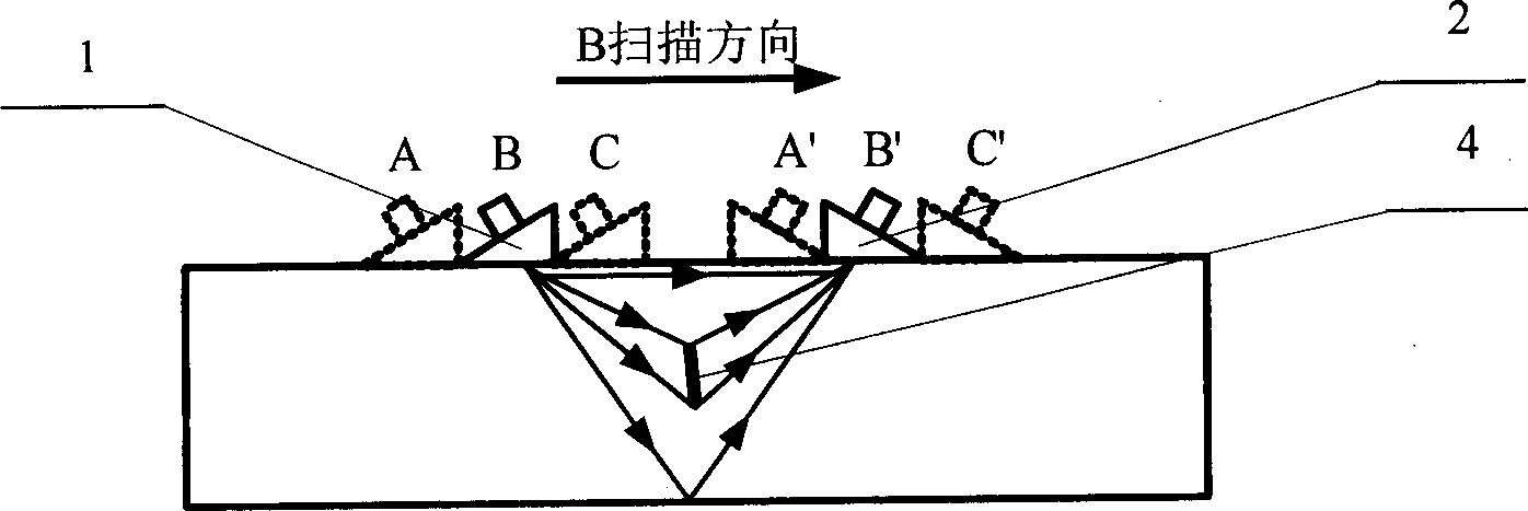
[0031] The first step is to first place the area to be inspected of the plate and its structural weld between the transmitting probe and the receiving probe, and first perform a D scan on the inspected area to determine the approximate location of the defect; set the scan step of the probe, Carry out a B-scan over the defect, and the detection system will receive the detection data of the probe to generate the original B-scan image to be processed, such as Image 6 As shown; where, the lateral wave propagating along the shallower depth below the surface of the plate and structural weld corresponds to the ho...


PUM


Abstract

The invention relates to an ultrasonic transit time test method based on synthesis aperture focus in the field of the ultrasonic wave nondestructive inspection of the panel and brazing seam fault. It uses the ultrasonic transit time to obtain the initial B scan image, dose linear process to B scan image and establishes the ultrasonic transit time method B scan image reconstruction math model based on synthesis aperture focus according to the forming course of the B scan image and the geometry relation of the probe and the fault location, at last it achieves the linear-synthesis aperture focus (L-SAFT) reconstruction of the image.

Description

technical field [0001] The invention relates to the field of ultrasonic non-destructive detection of defects in plates and welds. Background technique [0002] Ultrasonic time of flight method, referred to as ultrasonic TOFD (Time of Flight Diffraction), is a detection method based on receiving the diffraction signal at the end of the defect to locate and quantify the defect. This method can judge the buried depth size of defects in plates and welds and the size of defects themselves. However, using the D-scanning method of this method for detection, when the defect end is not on the perpendicular line between the two probes, there will be a large error in its positioning. During B-scanning, although the end of the defect is located on the vertical line between the two probes at a certain moment, because the sound beam of the ultrasonic transducer has a certain coverage width, the defect is arc-shaped in the B-scan image. The horizontal resolution of the machine is low, an...

Claims


Application Information

Patent Timeline
IPC IPC(8): G01N29/12G01N29/07G06F19/00
Inventor 刚铁迟大钊袁媛
Owner HARBIN INST OF TECH
Why Eureka
Try Eureka