
Quantum spot/quantum well light emitting diode

A technology of light-emitting diodes and quantum wells, which is applied in the direction of electrical components, circuits, semiconductor devices, etc., can solve the problems of reducing product yield, improving technology and cost, increasing process difficulty, etc., and achieves the effect of reduced area and good color rendering

Inactive Publication Date: 2006-07-19
IND TECH RES INST
View PDF0 Cites 6 Cited by
  • Summary
  • Abstract
  • Description
  • Claims
  • Application Information

AI Technical Summary

Problems solved by technology

However, since the wafer bonding process is added in the production process of this light source, the absorption caused by the two-chip interface will reduce its luminous efficiency, indirectly raise the threshold of its technology and cost, and also increase the difficulty of the process and reduce the product quality. yield

Method used


Image

  • Quantum spot/quantum well light emitting diode
  • Quantum spot/quantum well light emitting diode
  • Quantum spot/quantum well light emitting diode

Examples


Embodiment Construction

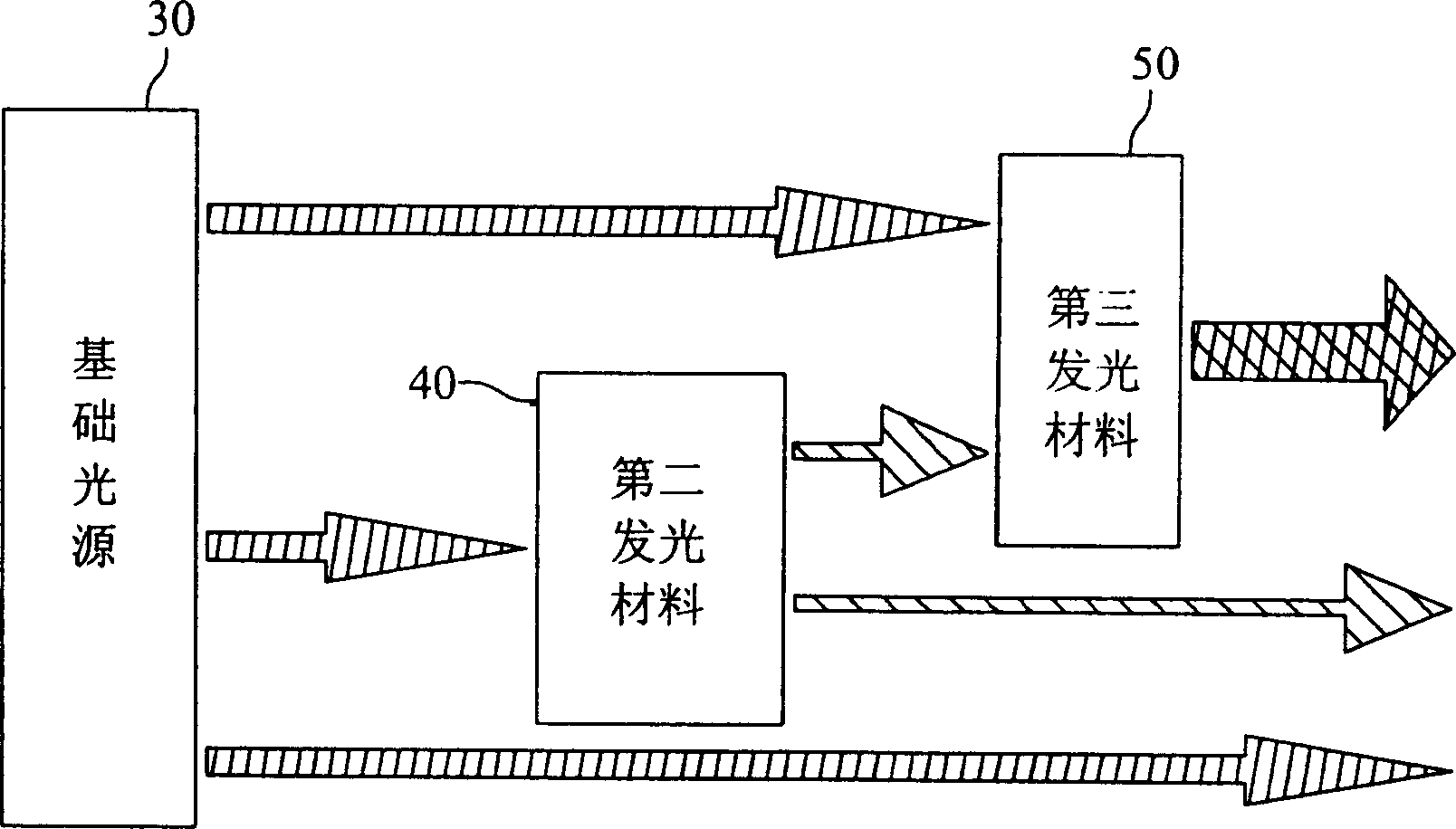
[0041] Please refer to figure 2 As shown, the quantum dot / quantum well light-emitting diode of the present invention utilizes the reaction of recycling photons, and uses part of the light emitted by a basic light source 30 to respectively excite a second luminescent material 40 and a third luminescent material 50 (the second luminescent material 50). The second luminescent material 40 and the third luminescent material 50 can absorb the energy of the basic light source 30 wavelength bands to emit light of different colors), of course, part of the light emitted by the second luminescent material 40 can also be used to excite the third luminescent material 50, and the light of three colors emitted by the basic light source 30, the second luminescent material 40 and the third luminescent material 50 can produce the light output of the desired color after light mixing.

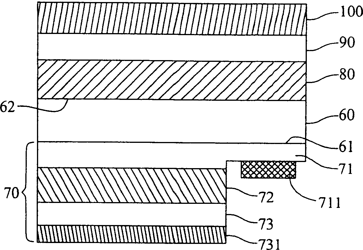
[0042] Please refer to Figure 3A Shown is a schematic structural diagram of the first embodiment of the quan...


PUM


Abstract

The invention relates to a quanta point / well light-emitting diode, which prepares a light-emitting diode on one side of basic plate; the second and third lighting layers on the another side of said basic plate. When a consequent bias voltage in correct amount is processed on said light-emitting diode, the first lighting layer can emit the first light, via which the second and third lighting layers can be excited to generate the second and third lights in different colors to be output; and when the first, second and third lights are mixed, the needed light can be output.

Description

technical field [0001] The invention relates to a light-emitting diode, in particular to a quantum dot / quantum well light-emitting diode free of fluorescent powder. Background technique [0002] A light emitting diode (Light Emitting Diode, LED) is a semiconductor light-emitting component. Unlike traditional incandescent bulbs, which heat the filament to glow with high current, light emitting diodes only need a very small current to stimulate considerable light. Light-emitting diodes use the combination of electron holes in semiconductor materials to display the energy released by emitting light; light-emitting diodes are small in size, long in life, low in driving voltage, low in power consumption, fast in response, and excellent in shock resistance. And the advantages of good monochromaticity, etc., are used as light-emitting components for various electrical appliances, information billboards, and communication products. According to the chip type and process control, va...

Claims


Application Information

Patent Timeline
Patent Type & Authority Applications(China)
IPC IPC(8): H01L33/00H01L33/08
Inventor 王德忠卓昌正蔡敬恩赖志铭
Owner IND TECH RES INST
Learn More