Novel anti-noise high-speed domino circuit

A domino and anti-noise technology, applied in logic circuits, electrical components, pulse technology, etc., can solve problems affecting speed and anti-noise ability

Inactive Publication Date: 2006-07-26
FUDAN UNIV
View PDF0 Cites 4 Cited by
  • Summary
  • Abstract
  • Description
  • Claims
  • Application Information

AI Technical Summary

Problems solved by technology

However, since KEEPER still exists in the stage of dynamic point level transition, increasing its size will definitely affect the speed, and reducing the size will affect the anti-noise ability, and the trade-off between speed and anti-noise still exists
So far, there is no circuit structure and technology designed for multi-input dynamic gate circuits that completely abandon the KEEPER structure.

Method used


Image

  • Novel anti-noise high-speed domino circuit
  • Novel anti-noise high-speed domino circuit
  • Novel anti-noise high-speed domino circuit

Examples


Embodiment Construction

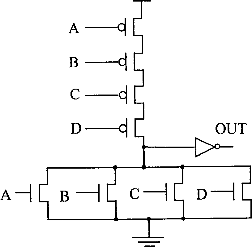
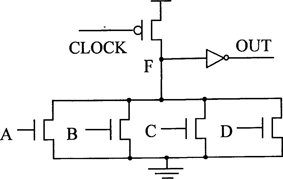
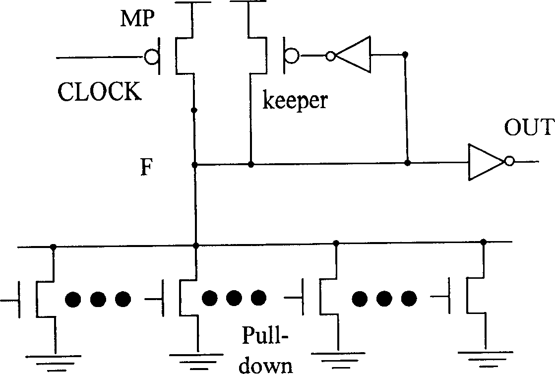
[0022] Figure 1 to Figure 4 This has been briefly explained in the background information.

[0023] Figure 5 It is a general block diagram of the structure proposed according to the working principle, which has been described in detail in the content of the invention above.

[0024] Image 6 yes Figure 5One of the special cases is a specific circuit structure diagram realized by the structure of a single pull-down network (the pull-down network has only one branch). Wherein G is an external dynamic point, F is an output dynamic point, that is, an internal dynamic point; the narrow pulse generator mainly includes PMOS transistors 1 and 2, NMOS transistor 3 and a delay network 11; and 10 is a pull-down network. Their connection relationship is: the clock is transmitted to the gates of NMOS transistor 3 and PMOS transistor 1 through the delay of delay network 11; PMOS transistors 1 and 2 are connected in series; the drain of PMOS transistor 2 and the drain of NMOS transist...


PUM


Abstract

This invention belongs to large scale digital integration circuit technique field and relates to one new anti-noise domino digital logic circuit, which Uses one thin impulse generator effective control dynamic points to make the output dynamic point keep original level in the noise situation to realize strong anti-noise property and Adopts pull network parallel structure to eliminate current compactor to work under high frequency.

Description

technical field [0001] The invention belongs to the technical field of large-scale digital integrated circuits, and in particular relates to an anti-noise high-speed domino circuit applicable to dynamic logic circuits. Background technique [0002] Dynamic CMOS logic is a widely used logic form. It is proposed on the basis of complementary CMOS logic in order to improve the operating speed of the circuit and reduce the number of PMOS transistors connected in series in complex gate circuits. Such as figure 1 Shown is a 4-input OR gate implemented in complementary CMOS, figure 2 Is its corresponding "footless transistor" (footless) dynamic CMOS gate circuit. The operation of the complementary CMOS gates is completely static, while the operation of the dynamic CMOS gates works under the clock pace coordination. When CLOCK is low level, the circuit is in the pre-charging stage, and the dynamic point F is charged to high level, at this time the input is invalid, and must be s...

Claims


Application Information

Patent Timeline
Patent Type & Authority Applications(China)
IPC IPC(8): H03K19/0944
Inventor 赖练章汤庭鳌林殷茵
Owner FUDAN UNIV
Why Eureka
Try Eureka