A high density plasma reactor

A plasma, plasma source technology, applied in the direction of plasma, semiconductor/solid-state device manufacturing, discharge tube, etc., can solve problems such as the reduction of electron energy

Active Publication Date: 2006-07-26
HELYSSEN
View PDF1 Cites 16 Cited by
  • Summary
  • Abstract
  • Description
  • Claims
  • Application Information

AI Technical Summary

Problems solved by technology

but if k z is too high, then the electron energy may drop below the ionization potential

Method used


Image

  • A high density plasma reactor
  • A high density plasma reactor
  • A high density plasma reactor

Examples


Embodiment Construction

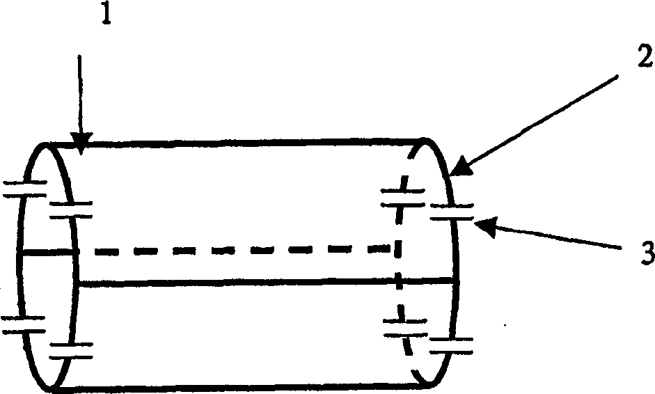
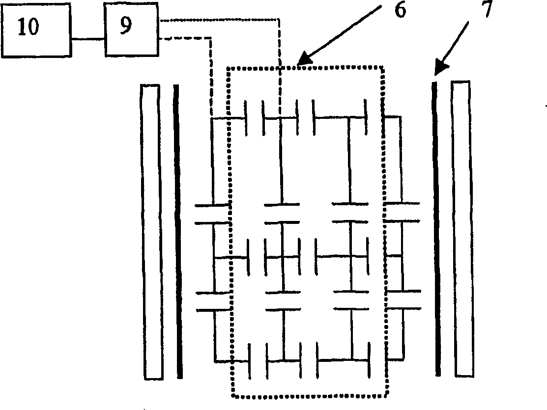
[0029] from figure 1 , 2, 4, 6 and 7, it can be seen that the first main structure of the present invention is the antenna setting:

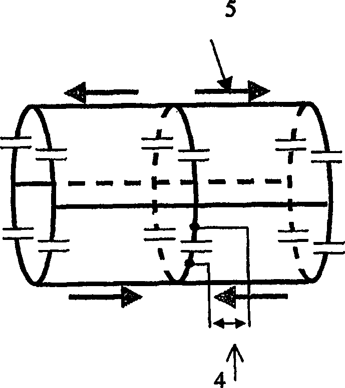
[0030] The radio frequency current flows through at least one pair of conductive rings (of any layout) 2 and the axial conductive element 1 . In this way the current flows according to the 5 figure 2 setting. An RF voltage is supplied from an RF power supply 4 .

[0031] One characteristic of coils is related to excitation. Single excitation point excitation of the RF coil results in a linearly polarized magnetic field B. Using one of the possible settings (see figure 1) achieves 90-degree phase-shifted excitation in a direct manner. 90 degree phase shift excitation can be accomplished by exciting the coils at two input capacitors 3 placed at right angles to each other along the circumference of a conductive ring element 2 . In addition, to achieve the desired circular polarization, the radio frequency sources used to excite the coil at ...


PUM


Abstract

The high density RF plasma source of this invention uses a special antenna configuration to launch waves at frequency such as 13,56MHz. The tunability of this antenna allows to adapt actively the coupling of the RF energy into an evolutive plasma as found in plasma processings in semiconductor manufacturing. This plasma source can be used for the following applications : plasma etching, deposition, sputtering systems, space propulsion, plasma - based sterilization , plasma abatement systems. In another embodiment, the plasma source is in conjunction with one or several process chambers , which comprise an array of magnets and RF coils too . These elements can be used, on one hand, for plasma confinement or the active plasma control (Plasma rotation ) thanks to feedback control approach , and one the other hand, for in situ NMR Monitoring or analysis such as moisture monitoring inside a process chamber , before or after the plasma process, or for in situ NMR Inspection of wafers or others workpieces.

Description

technical field [0001] The present invention relates to methods and apparatus for enhancing plasma sources and related processes. Background technique [0002] Helicon-wave discharges are known to efficiently generate high-density plasmas and have been used as high-density plasma tools in semiconductor processing (etching, deposition, sputtering...) [cf. Plasma Discharge by Lieberman M.A. and Lichtenberg A.J. Principles and Handling of Materials, New York, 1994 by J.Wiley & Sons Press], Space Engines, and Basic Plasma Experiments. Plasma is usually generated in a cylindrical vacuum vessel located in a longitudinal uniform magnetic field of 100-300G or higher. Electromagnetic energy is transferred to a plasma source at a frequency of 1-50 MHz, typically 13.56 MHz for plasma processing operations. With the help of specially shaped antennas, helical waves are generated in the plasma column. [0003] The most common antenna used to excite the helicon wave is the Nagoya III an...

Claims


Application Information

Patent Timeline
Patent Type & Authority Applications(China)
IPC IPC(8): H01J37/32H05H1/46
CPCH05H1/46H01L21/02H01L21/3065
Inventor 埃瑞克·舍瓦勒菲利普·吉杰恩
Owner HELYSSEN
Why Eureka
Try Eureka