Position sensorless control algorithm for AC machine

A motor and controller technology, applied in motor control, motor generator control, electronically commutated motor control, etc., can solve problems such as reducing the cost of electric vehicles

Active Publication Date: 2006-07-26
GENERAL MOTORS COMPANY
View PDF0 Cites 14 Cited by
  • Summary
  • Abstract
  • Description
  • Claims
  • Application Information

AI Technical Summary

Problems solved by technology

Removing the feedback device from the motor control system will result in a considerable reduction in the cost of electric vehicles

Method used


Image

  • Position sensorless control algorithm for AC machine
  • Position sensorless control algorithm for AC machine
  • Position sensorless control algorithm for AC machine

Examples


Embodiment Construction

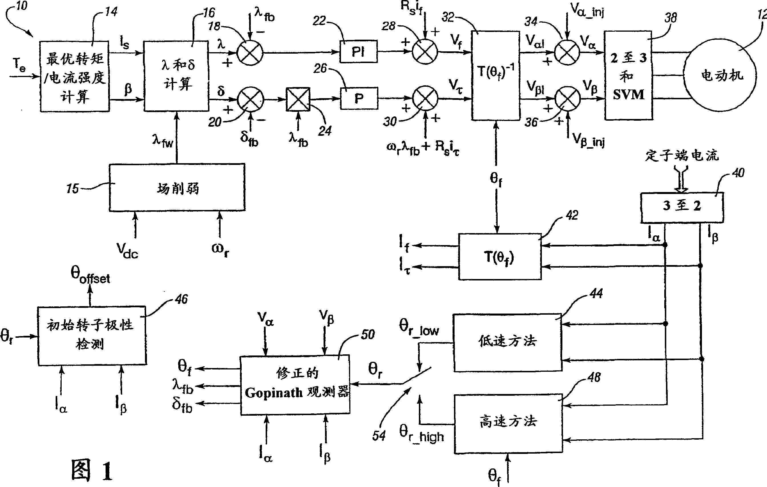
[0011] Figure 1 is a schematic diagram of a preferred embodiment of a control system 10 of the present invention. The control system 10 is shown as a series of block diagrams representing software executing in a controller, microprocessor or similar device to control the motor 12 . In the preferred embodiment of the present invention, the controller is a vehicle powertrain controller controlling electric motor 12, but any other motor control application is considered to be within the scope of the present invention. Electric motors may include drive technologies such as, but not limited to, AC motors, synchronous reluctance motors, induction motors, and interior permanent magnet motors. The input to the control system is the torque command T generated by the vehicle controller e . The torque command T e Processed by the optimal torque / current intensity calculation block 14 to generate the corresponding stator current command I required to generate the desired electromagnetic...


PUM


Abstract

The present invention provides a control system for an electric motor having a stator and rotor including an inverter for providing power to the electric motor, a controller for controlling the inverter, a low speed control block to estimate the rotor angular position using stator current components operating in the controller, a high speed control block to estimate the rotor angular position using stator current components and stator flux position operating in the controller, a transition switch in the controller to vary operation between the low speed control block and the high speed control block, and where the inverter is controlled by six step operation.

Description

technical field [0001] The present invention relates to the control of electric motors, and more particularly, the present invention relates to a method and apparatus for sensorless position control of electric motors. Background technique [0002] Traditional motor control systems typically include feedback devices or position sensors such as resolvers or encoders to provide speed and position information to the motor. Feedback devices and their associated interface circuitry add to the cost of the motor control system, and these costs can become prohibitive in high volume applications such as automotive applications. Additionally, the position sensor and its associated wiring harness add to the complexity and assembly time of the vehicle's electric drivetrain. [0003] Electric vehicles powered by fuel cells, batteries and hybrid systems including electric motors are becoming more common in the automotive market. As production volumes of electric vehicles increase, the c...

Claims


Application Information

Patent Timeline
Patent Type & Authority Applications(China)
IPC IPC(8): H02P23/14H02P6/18H02P21/00
CPCH02P21/0089H02P6/181H02P2203/05H02P21/0046H02P21/12H02P2207/05H02P6/18H02P21/00H02P21/28
Inventor S·E·舒尔茨N·R·帕特尔J·M·纳加施马S·K·苏尔B·-H·贝
Owner GENERAL MOTORS COMPANY
Why Eureka
Try Eureka