High-voltage side mutual inductance energy-acquiring device of high-voltage power transmission line

A high-voltage transmission line, mutual inductance energy harvesting technology, applied in the direction of circuit devices, output power conversion devices, circuits, etc., can solve the problems of difficult on-site maintenance, expensive laser source, low precision and accuracy of DC power supply, etc., to achieve Highly Accurate Effects

Inactive Publication Date: 2010-10-20
WUHAN NARI LIABILITY OF STATE GRID ELECTRIC POWER RES INST
View PDF9 Cites 16 Cited by
  • Summary
  • Abstract
  • Description
  • Claims
  • Application Information

AI Technical Summary

Problems solved by technology

For battery power supply, the simple but obvious disadvantage is that the battery needs to be replaced after long-term use; and for solar power supply, because the current solar technology still needs to further improve its conversion efficiency, especially in long-term rainy weather, its battery life The ability cannot be guaranteed; there are also some deficiencies in methods such as laser power extraction and capacitor voltage division.
For example, foreign ABB companies and products that have appeared in China all adopt laser energy delivery schemes. The disadvantages in the implementation of such schemes are: the life cycle of the laser source is short, only 8000-10000 hours; the price of the laser source is expensive; on-site maintenance is difficult. and many more
At present, the problems that need to be solved urgently in this power supply method include: 1) To provide stable output in the case of wide range changes in line current; 2) Long-term stable operation with low heat consumption
In Chinese patent 200810212134.4 "High-voltage induction energy harvesting power supply and method of obtaining power from high-voltage line for power supply", the compensation unit is used to solve the above problems, and the second electromotive force different from the first electromotive force is induced from the high-voltage line, and passed through the second electromotive force A part of the first electromotive force is reversely compensated to make the final output voltage stable, but the disadvantage of this method is that the precision and accuracy of the obtained DC power supply are low

Method used


Image

  • High-voltage side mutual inductance energy-acquiring device of high-voltage power transmission line
  • High-voltage side mutual inductance energy-acquiring device of high-voltage power transmission line
  • High-voltage side mutual inductance energy-acquiring device of high-voltage power transmission line

Examples


Embodiment Construction

[0017] Below in conjunction with accompanying drawing, the present invention is described in more detail.

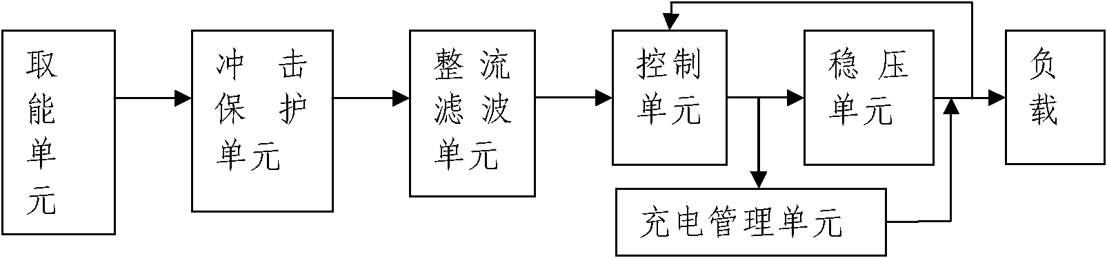
[0018] The present invention is composed of an energy-taking unit (mainly composed of an iron core (U-shaped or O-shaped) with an air gap and a coil), an impact protection circuit, a filter rectifier circuit, a control unit circuit, a voltage stabilizing circuit, a charging management circuit and load composition. Its specific circuit connection is mainly to handle the coordination relationship of the control, voltage stabilization, and lithium battery charging management circuits.

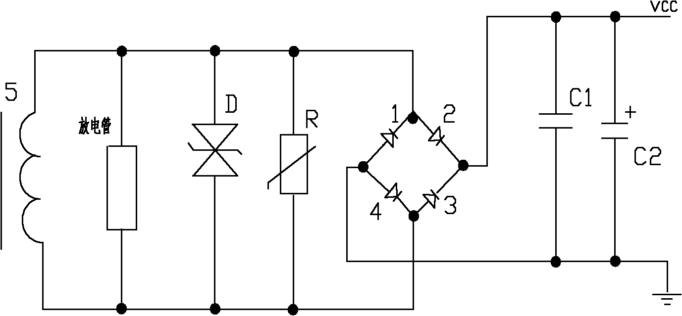
[0019] In the front part of the present invention, the iron core wound with enameled wire (that is, the composed coil) is placed on the high-voltage transmission line, so that the induced electromotive force is obtained at both ends of the coil. A bidirectional gas discharge tube, a bidirectional transient suppression diode (TVS) D and an adjustable varistor R are connected in parallel at b...


PUM


Abstract

The invention relates to a high-voltage side mutual inductance energy-acquiring device of a high-voltage power transmission line, comprising an energy-acquiring unit, an impact protective circuit, a filtering and rectifying circuit, a control unit circuit, a charging management circuit and a voltage-stabilizing circuit. By adopting a feedthrough strip coil with a certain turn number, enough energy can be acquired under the condition of low current, and the conversion and the balance of energy can be realized through a high-speed control unit consisting of a comparator, an MOS (Metal Oxide Semiconductor) tube and a high-power resistor under the condition of heavy current, thereby providing a safe, stable and high-precision direct current power supply for power transmission line motoring under the condition of power transmission current in a wide range.

Description

technical field [0001] The invention relates to the field of on-line monitoring of substations and power transmission and distribution lines, in particular to a high-voltage side mutual inductance energy harvesting device for state monitoring of substations and power transmission and distribution lines. Background technique [0002] When monitoring the status of substations and transmission and distribution lines online, the power supply problem of high-voltage side electronic equipment has become a major obstacle hindering the development of this technology. At present, the power supply methods on the high-voltage side that are widely used mainly include: battery power supply, capacitor voltage division power supply, laser power supply, and solar power supply. For battery power supply, the simple but obvious disadvantage is that the battery needs to be replaced after long-term use; and for solar power supply, because the current solar technology still needs to further impro...

Claims


Application Information

Patent Timeline
Patent Type & Authority Applications(China)
IPC IPC(8): H02J17/00H02M7/12H02M1/32H01F38/20H02J50/10
Inventor 柳德伟俞坤师
Owner WUHAN NARI LIABILITY OF STATE GRID ELECTRIC POWER RES INST
Why Eureka
Try Eureka