
Heat imaging sensor for real-time closed-loop control

a closed-loop control and heat imaging technology, applied in the direction of optical radiation measurement, instruments, coatings, etc., can solve the problems of high-speed assembly machine downtime, high-speed operation of the valving mechanism of the hot glue gun, and inability to repeat and precise high-speed operation, so as to improve the signal-to-noise ratio and reduce the effect of threshold dri

Inactive Publication Date: 2008-01-17
DELCHER RAY C +2
View PDF18 Cites 16 Cited by
  • Summary
  • Abstract
  • Description
  • Claims
  • Application Information

AI Technical Summary

Benefits of technology

[0009] The present invention provides closed-loop control of a glue gun using thermal-infrared sensing. Key to this breakthrough is the development of a practical high-speed thermal-infrared sensor providing improved signal to noise ratio and reduced threshold drift.
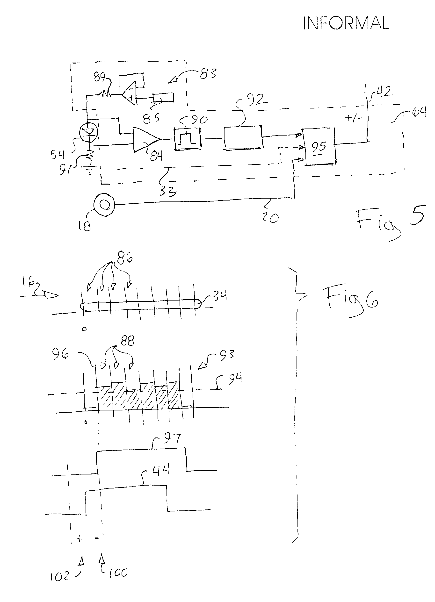
[0010] Specifically, the present invention provides a system including a hot glue gun receiving a trigger signal at a trigger time to actuate a dispensing of glue on a substrate at a dispensing time. A thermal-infrared sensor views a pattern of dispensed glue on the substrate by detecting a temperature difference between the substrate and the glue to produce a detection signal and a comparison circuit receives the detection signal to detect an error caused by variations between the trigger time and a dispensing time. A modification circuit modifies the trigger signal based on this error to reduce the detected error.

Problems solved by technology

Delays or advances in the dispensing time, as products move by the glue gun, can leave beads or strings of glue extending from the seams or create seams that are improperly or incompletely glued and hence sealed.
The dispensing of hot glue at times when the product is not properly aligned with the glue gun can dispense glue on the conveyor system creating costly downtime for high-speed assembly machines.
Repeatable and precise and high-speed operation of the valving mechanism of a hot glue gun is difficult.
The intrinsic variations in the response time of the valve place significant limits on the throughput of assembly machines using hot glue dispensers.
Unfortunately imaging of the glue beads at high speed is difficult because the glue is transparent or light in color and often dispensed on a light surface, for example, light paper stock.
This approach is not always practical for reasons of consumer acceptance or expense.
Practical thermal-infrared imagers are either relatively sluggish in performance, noisy, or require expensive and unreliable cryogenic cooling, and thus have not been used for real-time, closed-loop control but only for quality assessment purposes where the errors are analyzed off line and used to schedule maintenance for adjustment of the glue gun.

Method used


Image

  • Heat imaging sensor for real-time closed-loop control
  • Heat imaging sensor for real-time closed-loop control
  • Heat imaging sensor for real-time closed-loop control

Examples


Embodiment Construction

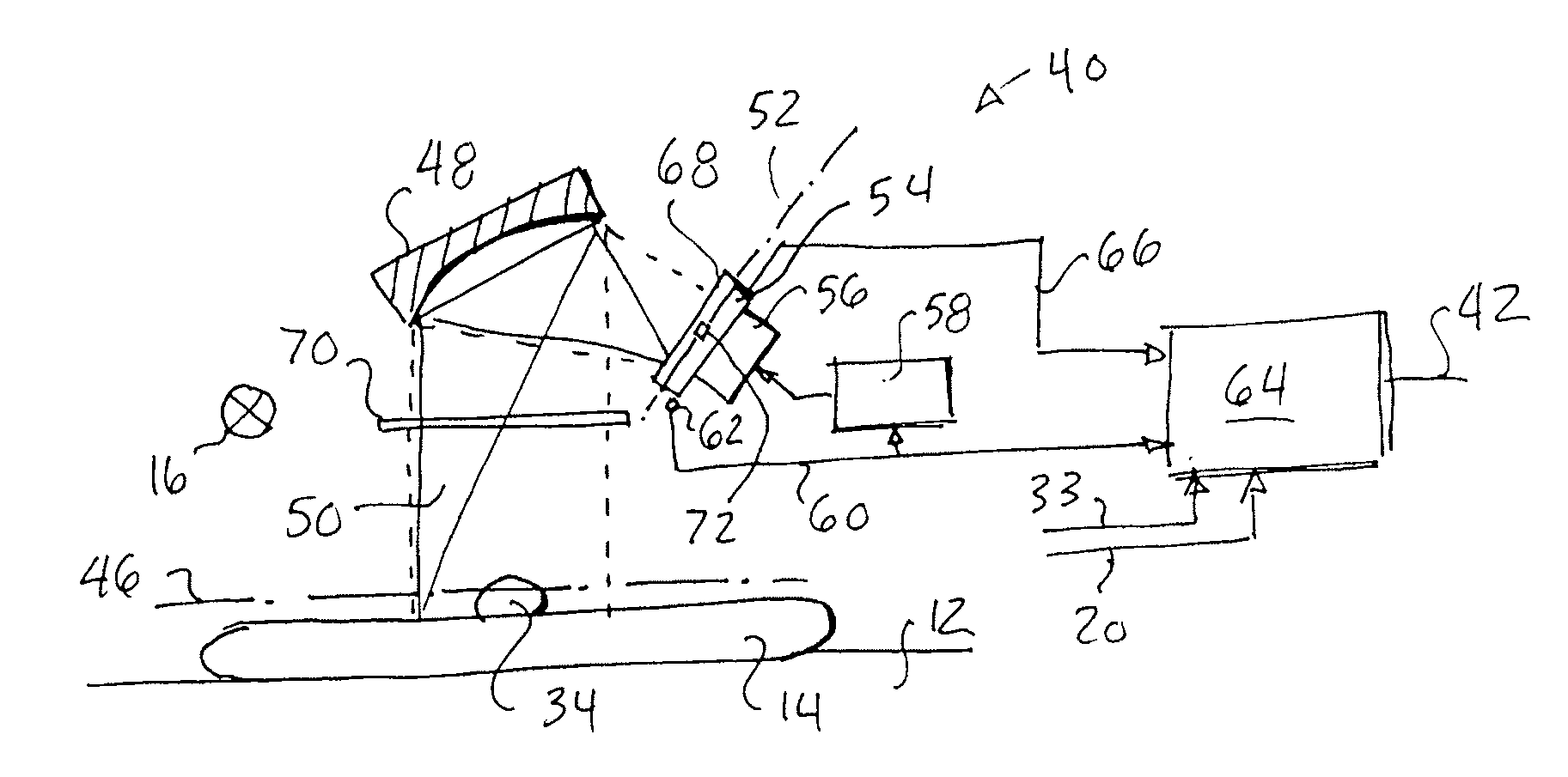
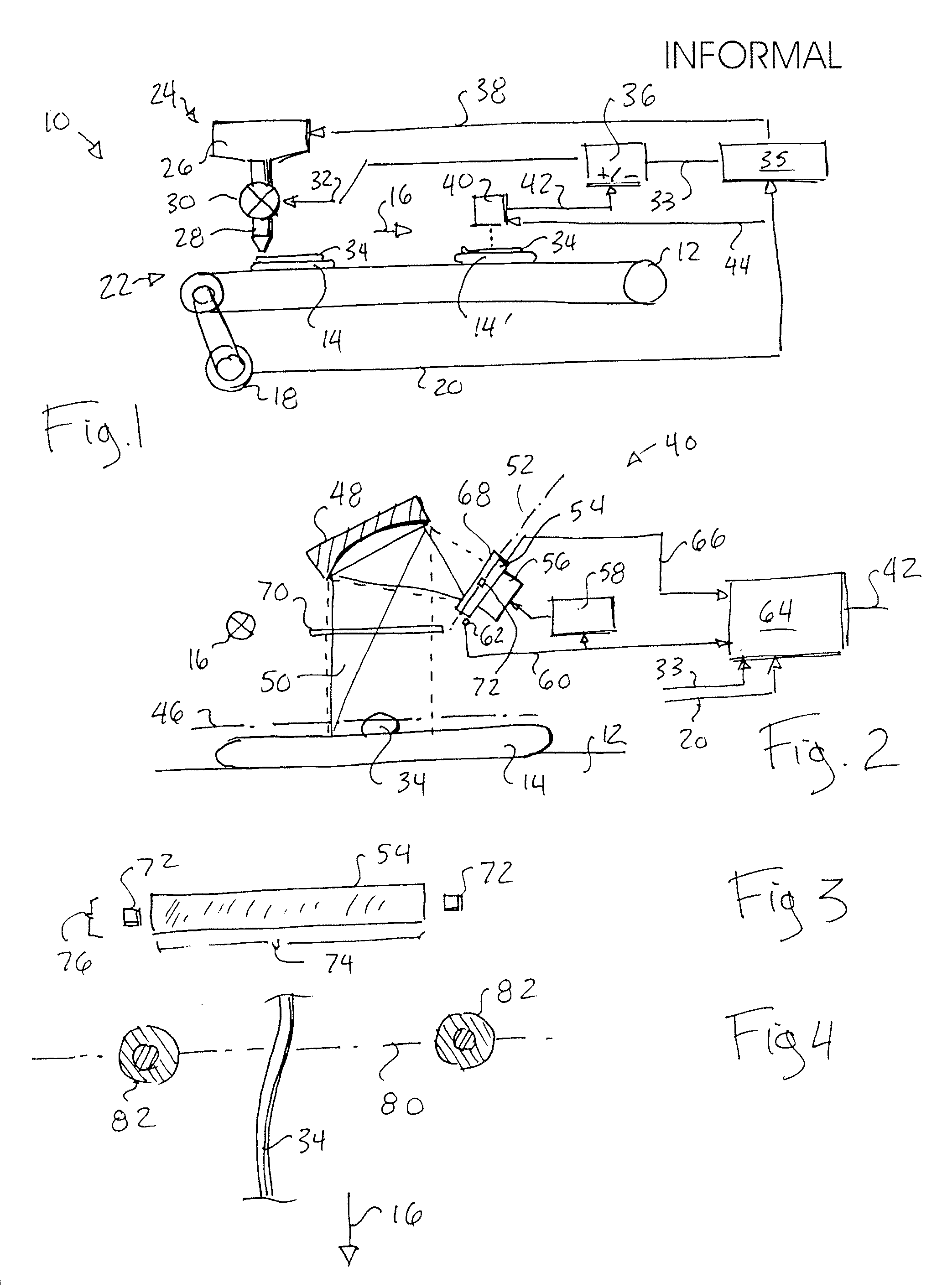
[0046] Referring now to FIG. 1, a hot glue dispensing assembly line 10 may include a conveyor belt 12 or the like moving substrates 14, such as products to be assembled, in a direction 16 as carried regularly by the conveyor belt 12. Conveyor belt 12 may be attached to an encoder 18 providing a displacement signal 20 indicating the absolute location of the substrates 14 along the line of the conveyor belt 12.

[0047] A glue gun 24 may be positioned at an upstream end 22 of the conveyor belt 12, the glue gun 24 having a pressurized hot glue reservoir 26 connected to a nozzle 28 by means of electrically actuated valve 30. The valve 30 may receive a trigger signal 32 to open the valve to cause a dispensing of glue through the nozzle 28 in a glue bead 34 on to substrate 14. As is understood in the art, the speed of response of the valve 30 will change, being dependent on the characteristics of the glue, including its viscosity and chemical formulation, as well as wear and heating of the ...


PUM


Abstract

A real-time timing correction system for high speed control of hot glue dispensing uses a thermal-infrared detector and a feedback control loop distinguishing dispensed hot glue from a substrate by heat emissions.

Description

CROSS REFERENCE TO RELATED APPLICATION [0001] This application claims the benefit of the U.S. provisional application 60 / 766,710 entitled: “Hot Glue And Thermal Web Sensor For Inspection And Control Of High-Speed Processes” filed on Feb. 7, 2006 and hereby incorporated by reference.STATEMENT REGARDING FEDERALLY SPONSORED RESEARCH OR DEVELOPMENT [0002] -- BACKGROUND OF THE INVENTION [0003] The present invention relates to systems for the real-time control of hot glue dispensing equipment and in particular to a closed-loop control system employing a thermal-infrared sensor for detecting variation in glue times. [0004] Hot glue dispensed from a hot glue gun may be used for the rapid automated assembly of products, for example, cardboard boxes, the latter which have joints held together with hot glue. Unlike conventional adhesives, hot glue provides fast setting times without the need for dangerous solvents or the mixing of multiple part formulations. The glue, when heated, may be dispe...

Claims


Application Information

Patent Timeline
Patent Type & Authority Applications(United States)
IPC IPC(8): G01J5/30
CPCB05C5/0225B05C11/1042B05C11/1021B05C11/1005
Inventor DELCHER, RAY C.KHOSHNEVISAN, MOHSENWEN, BING
Owner DELCHER RAY C
Learn More