Automatic rotary plastic bottle blowing machine

A fully automatic blow molding machine technology, applied in the field of processing equipment for hollow plastic containers, can solve the problems of low production efficiency, difficult control, troublesome installation and transportation, etc., and achieve the effects of fast production speed, simple structure and convenient transportation

Inactive Publication Date: 2006-08-02
蔡佳祎
View PDF0 Cites 4 Cited by
  • Summary
  • Abstract
  • Description
  • Claims
  • Application Information

AI Technical Summary

Problems solved by technology

Existing fully automatic plastic blow molding machines can be divided into three types. The first type is that the heating device and the stretch-blow mechanism are installed independently. The disadvantage is that the pick-up and delivery of the manipulator needs to complete multiple actions in different directions, so the structure is complex and the control is difficult. There is only one stretching and blowing station, the speed is slow, and the production efficiency is low.
The second type is to install the heating device and the stretch blowing mechanism in the same running track, which is divided into a feeding section (running section), a heating section, and a blowing section. The track stroke is very long, the volume is large, and the manufacturing cost is high. Installation, transportation It is very troublesome, but there is only one set of blowing mechanism, and the production efficiency of single-station blowing is low
The third type is that the heating device and the stretch blowing mechanism are installed in groups. The heated bottle tube is transferred from the heating device to the stretch blowing mechanism through the middle rotating disc. Although the transfer of the rotating disc is not as complicated as the first type of manipulator, it increases the volume. , increased structural complexity, high manufacturing cost, troublesome installation and maintenance

Method used


Image

  • Automatic rotary plastic bottle blowing machine
  • Automatic rotary plastic bottle blowing machine
  • Automatic rotary plastic bottle blowing machine

Examples


Embodiment Construction

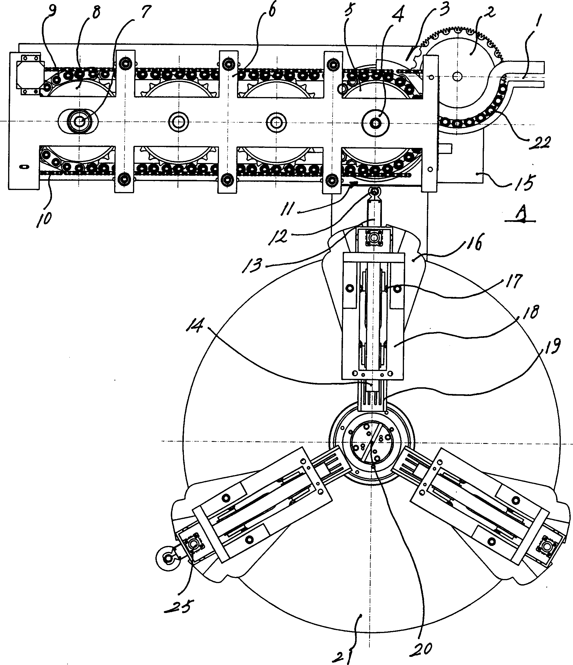
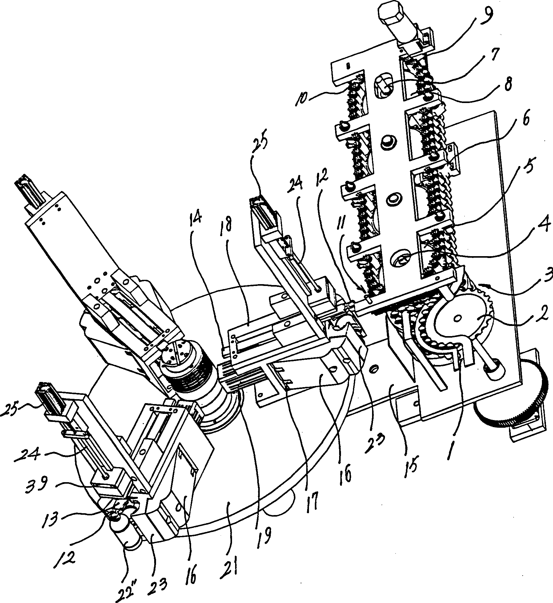
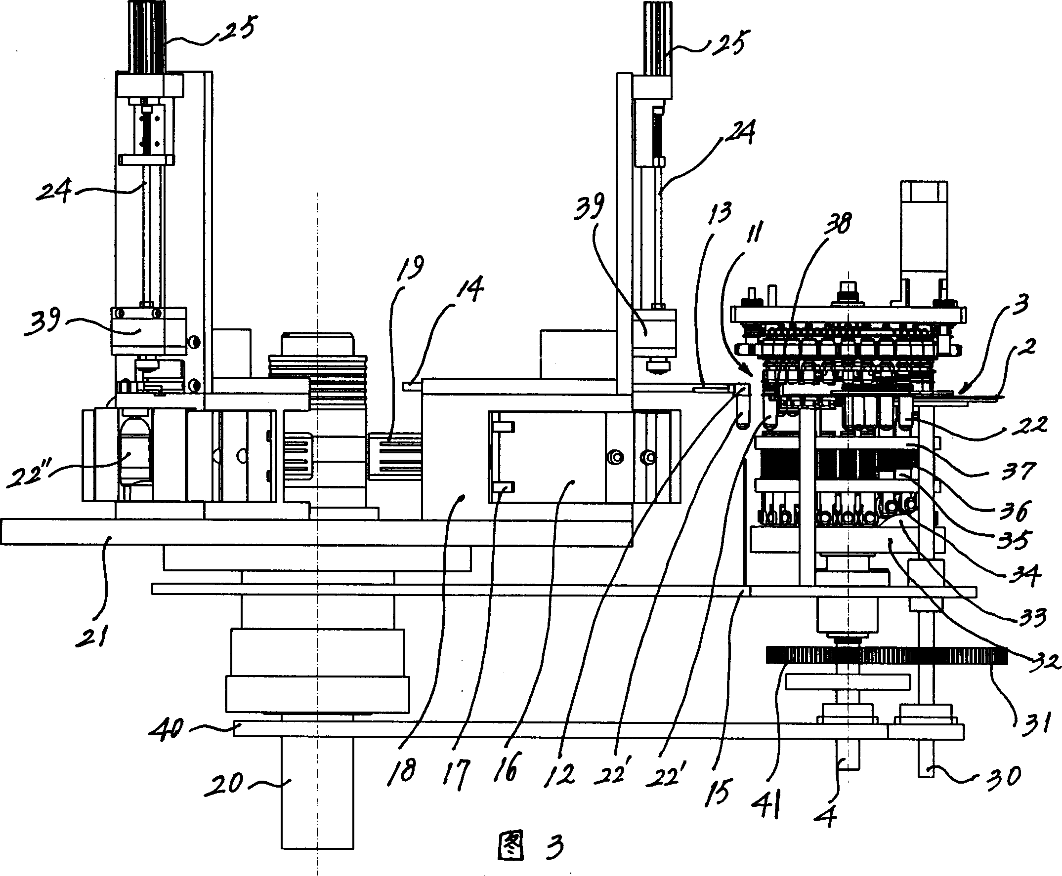
[0010] The invention discloses a rotary direct-taking full-automatic plastic bottle blowing machine, which can be divided into two parts: a heating device for plastic bottle tubes and a bottle blowing mechanism for stretch blow molding. Mechanism and feeding mechanism, the basic structure of the heating device is as follows figure 1 , figure 2 As shown in Fig. 3, the driving shaft 4 drives the driving sprocket 5, drives the driven sprocket 8 through the chain 9, the driven sprocket has the driven shaft 7, and there is a bottle tube supporting pipe in the chain, and a heating device for installation is arranged. Support 6, can make the rotation chain 10 etc. of supporting pipe tool rotation, but the specific type of heating device has various structures, and this technical scheme is owing to can adopt multi-station, and production efficiency is high, and the speed of requiring heating is also fast, so The heater can be multiple back and forth heating channels (attached figur...


PUM


Abstract

The automatic rotary plastic bottle blowing machine consists of a heater and a bottle pulling and blowing formation mechanism. The heater has a plastic bottle pipe feeding mechanism and a discharge mechanism; and the bottle pulling and blowing formation mechanism has mold plates on the frame, a cylinder-link rod assembly to drive the mold plates to open and close, a mold inside the mold plates, a pulling cylinder to drive the pulling rod and a blowing cylinder n the frame, a bottle blowing unit on the rotary plate, pipe taking pincers over the mold plates and the mold to take the heated plastic bottle pipe from the heater to the mold. The technological scheme has the pipe taking pincers to take the heated plastic bottle pipe from the heater to the mold directly without intermediate conveying mechanism and thus has simple structure and high production efficiency.

Description

technical field [0001] The invention relates to a rotary direct-taking full-automatic plastic bottle blowing machine, which belongs to processing equipment for hollow plastic containers, and can be used for processing mineral water bottles, medicine bottles, oil bottles and cosmetic bottles, etc., for example. Background technique [0002] Plastic raw materials (such as PET, etc.) are used to process hollow containers such as mineral water bottles, medicine bottles, and cosmetic bottles. The injection stretch blowing process can be applied. First, the plastic raw materials are injected into bottle tubes by the injection molding machine, and then the bottle tube is heated twice by the heating device. Finally, it is blown and molded by a stretch-blow machine. The heating device for heating the bottle tube is combined with the stretch-blow mechanism for stretch-blow molding, and the bottle tube can be automatically conveyed, which is called a fully automatic p...

Claims


Application Information

Patent Timeline
Patent Type & Authority Applications(China)
IPC IPC(8): B29C49/28B29C49/08B29C49/42B29C49/64
Inventor 蔡佳祎
Owner 蔡佳祎
Why Eureka
Try Eureka