Co-axial middle-set motor driving device of electric vehicle

A mid-mounted motor and driving device technology, applied in electric vehicles, electromechanical devices, motors, etc., can solve problems such as unreasonable center of gravity, poor reliability, and short mileage, and achieve reasonable center of gravity, fast starting speed, and output torque big effect

Active Publication Date: 2006-08-09
DONGGUAN JINGCHENG MOTOR TECH CO LTD
View PDF0 Cites 12 Cited by
  • Summary
  • Abstract
  • Description
  • Claims
  • Application Information

AI Technical Summary

Problems solved by technology

[0003] 1. The friction wheel transmission type has simple structure, easy manufacture, low cost and convenient maintenance, but its efficiency is low, the shape is poor, the tires are seriously worn, and it cannot adapt to wet and muddy road conditions. This type of transmission is basically eliminated.
[0004] 2. The side-mounted chain (or shaft) transmission type is often used in the transformation of old bicycles. It has poor appearance, low efficiency, and poor reliability. It cannot be popularized and applied. OEMs cannot use this type of motor
[0005] 3. The front axle transmission type is that the motor hub is installed on the front axle. The center of gravity is unreasonably distributed, not light, and the handlebar cannot be turned flexibly. If the magnetic tile falls off, it will suddenly get stuck on the high-speed rotating motor rotor. It is very easy to cause safety accidents, and manufacturers do not use it
[0006] 4. The transmission type of the rear wheel shaft. At present, most of the vehicle manufacturers adopt this transmission type. The motor and the rear axle are integrated and placed at the rear of the vehicle. The center of gravity is unreasonable, the energy consumption is large, the efficiency is low, the mileage is short, and maintenance Inconvenient, poorly sealed bearings, and shortened motor life
The low-speed hub drive was once very popular because of its low cost and high noise. However, due to its motor characteristics, it has poor wind resistance and climbing performance, and consumes more power. In addition, it will generate greater electromagnetic resistance when riding without electricity. Difficulty for human riding

Method used


Image

  • Co-axial middle-set motor driving device of electric vehicle
  • Co-axial middle-set motor driving device of electric vehicle

Examples


Embodiment Construction

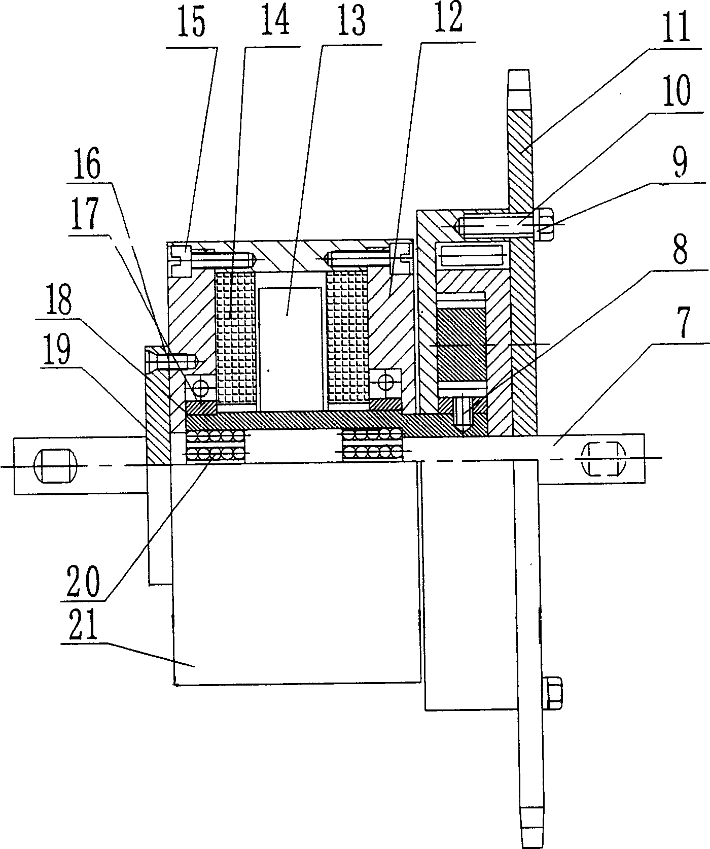
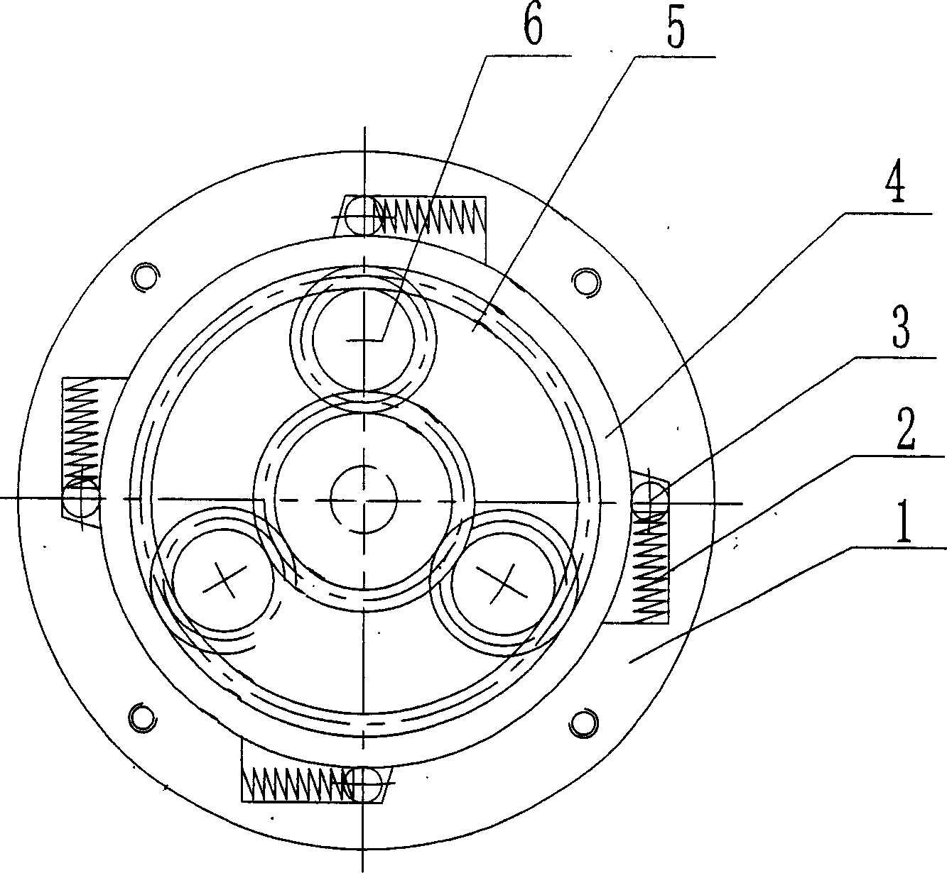
[0014] Such as figure 1 As shown, what this embodiment adopts is a brushless motor. The left half is the motor drive mechanism, and the right half is the variable speed clutch mechanism. Pedal is installed in the two ends of central shaft 7, and central shaft 7 is installed in the axle position of vehicle frame by bearing. The hollow shaft 18 is concentric with the central shaft 7 for the rotor shaft of the motor. It is installed on the central shaft 7 through two sets of multi-row steel balls 20, the rotor permanent magnet 13 is fixed in the middle of the hollow shaft 18, the coils 14 on both sides of the rotor are fixed in the inner cavity of the motor casing 21, and the casing 21 passes through two bearings 17 Fixed on both ends of the hollow shaft 18. When the coil 14 supplies power, the rotor permanent magnet 13 rotates under the action of the magnetic force line and drives the hollow shaft 18 to rotate around the central axis 7 at a high speed, and the power is driven...


PUM


Abstract

The disclosed drive unit is composed of two parts: electric drive and speed change. Rotor shaft of electromotor is a hollow shaft, which is concentric to central axis of pedal plate. When power off, the pedal plate drives electric motor bicycle running. Magnetic resistance force does not interfere bicycle running. When power on, rotor is rotated at high speed under action of magnetic field. Being sheathed on the shaft of pedal plate, the hollow rotor shaft drives rotation of sun gear of speed change gear. Through three pieces of planet wheel, one-way internal gear, and wedge shaped clutch, the sun gear drives rotation of outer shell of speed change gear. Chain wheel installed on the outer shell through chain drives rear wheel forward. Features are: compact structure, reasonable center of gravity, and convenient installation and maintenance.

Description

technical field [0001] The invention relates to a coaxial central motor driving device for an electric vehicle, which is especially suitable for various electric bicycles and electric tricycles with central chain transmission or shaft transmission. Background technique [0002] At present, the driving types of electric motors applied to electric bicycles or electric three-wheels generally include friction wheel transmission, side-mounted type, and front and rear hub transmission. The motors of these four transmission types have the following problems: [0003] 1. The friction wheel transmission type has simple structure, easy manufacture, low cost and convenient maintenance, but its efficiency is low, the shape is poor, the tires are seriously worn, and it cannot adapt to wet and muddy road conditions. This type of transmission is basically eliminated. . [0004] 2. The side-mounted chain (or shaft) transmission type is often used in the transformati...

Claims


Application Information

Patent Timeline
Patent Type & Authority Applications(China)
IPC IPC(8): H02K7/10H02K7/116
CPCY02T10/641Y02T10/64
Inventor 宋宣儒秦德国
Owner DONGGUAN JINGCHENG MOTOR TECH CO LTD
Why Eureka
Try Eureka