Foldable space manipulator
A technology of manipulators and space, applied in the field of manipulators, can solve problems such as the folding characteristics of manipulator systems in difficult spaces, poor performance, and threat to astronauts’ lives.
- Summary
- Abstract
- Description
- Claims
- Application Information
AI Technical Summary
Problems solved by technology
Method used
Image
Examples
specific Embodiment approach 1
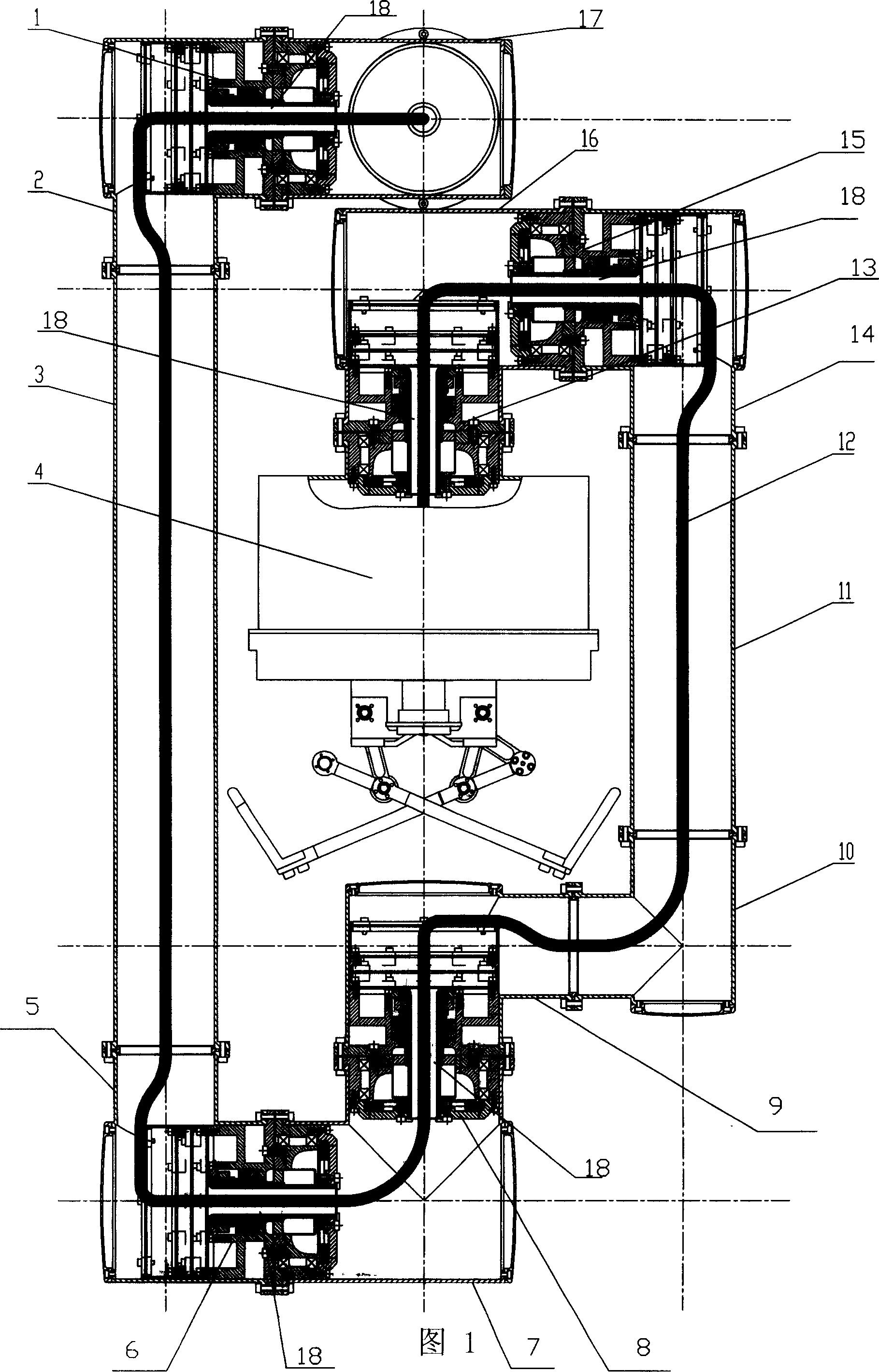
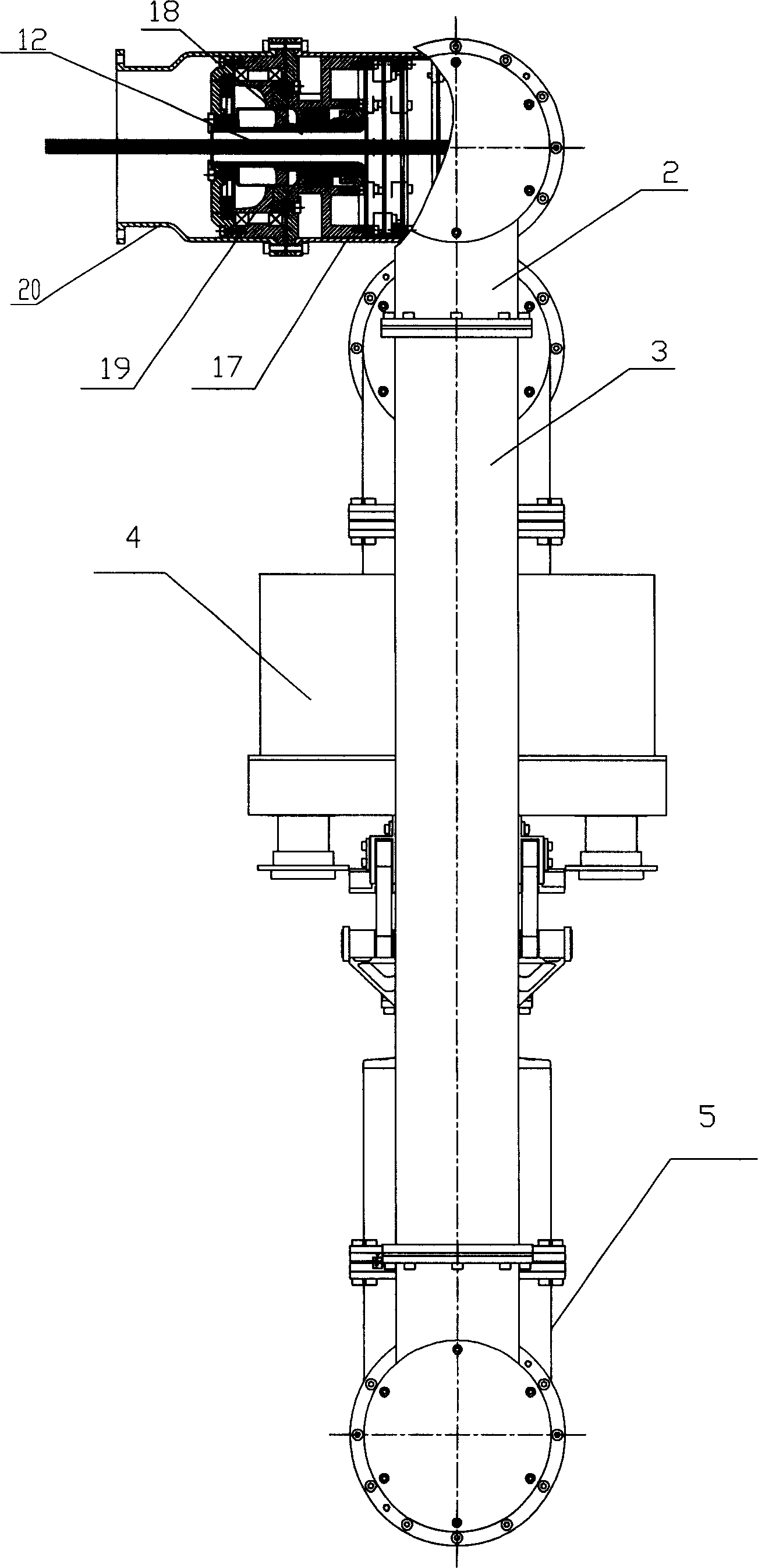
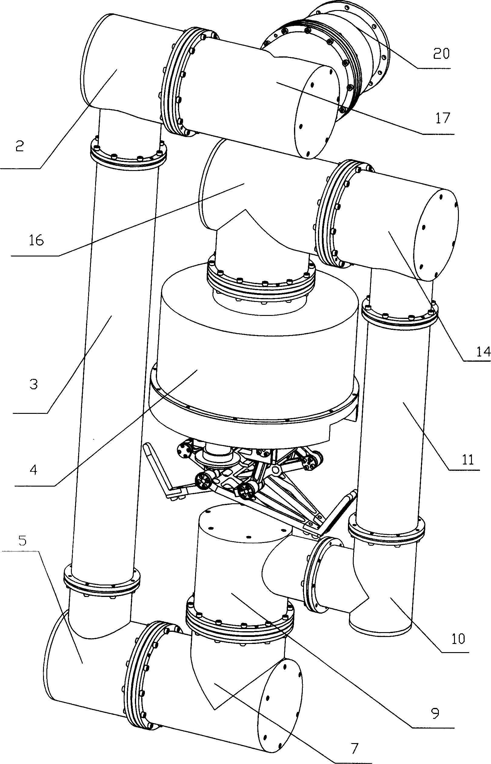
[0005] Specific implementation mode one: (referring to Fig. 1~ image 3 ) This embodiment consists of the first modular joint 1, the second modular joint 6, the third modular joint 8, the fourth modular joint 13, the fifth modular joint 15, the sixth modular joint 19, single degree of freedom Claw 4, lead wire 12, the first joint shell 2, the second joint shell 5, the third joint shell 7, the fourth joint shell 9, the fifth joint shell 14, the sixth joint shell 16, the seventh joint shell 17, the The eight-joint shell 20, the first arm 3, the second arm 10 and the third arm 11; the outer wall at one end of the sixth modular joint 19 is fixedly connected to the inner wall at one end of the eighth joint shell 20, and the sixth modular joint 19 The outer wall at the other end is fixedly connected to the outer wall at one end of the seventh joint shell 17, the outer wall at one end of the first modular joint 1 is fixedly connected to the inner wall at the other end of the seventh ...
specific Embodiment approach 2
[0006] Specific implementation mode two: (see Figure 4~7) The first modular joint 1 , the second modular joint 6 , the third modular joint 8 , the fourth modular joint 13 , the fifth modular joint 15 and the sixth modular joint 19 of this embodiment are respectively controlled by the joint mechanism , a motor device and a sleeve 31; the joint mechanism is composed of a torque sensor 1-1, a position sensor, a harmonic reducer, a bearing 1-4, a bearing inner ring seat 1-5, a bearing outer ring seat 1-6 and Connecting flange 1-7, the harmonic reducer is composed of wave generator 1-3-1, rigid wheel 1-3-2 and flexible wheel 1-3-3, and the motor device is composed of DC Brush motor, magnetic encoder 2-2, drive circuit board 2-3, control circuit board 2-4, power circuit board 2-5, interface circuit board 2-6, first bracket 2-7, second bracket 2- 8. The third bracket 2-9 and the pressure ring 2-10 are composed, and the brushless DC motor is composed of a motor shaft 2-1-1, a motor ...
specific Embodiment approach 3
[0008] Specific implementation mode three: (see Figure 5 ) The difference between this embodiment and the specific embodiment one is: the motor device of this embodiment also has a digital Hall sensor 2-15; the digital Hall sensor 2-15 is installed in the motor casing 2-1-2 and fixedly connected with the motor stator 2-1-6. Redundant measurement of the motor position: it can be measured separately through the digital Hall sensor 2-15 and the magnetic encoder 2-2, which can improve the reliability of the system. If one is broken, the other can work independently.
PUM
 Abstract
Description
Claims
Application Information
 - R&D
- Intellectual Property
- Life Sciences
- Materials
- Tech Scout
- Unparalleled Data Quality
- Higher Quality Content
- 60% Fewer Hallucinations
Browse by: Latest US Patents, China's latest patents, Technical Efficacy Thesaurus, Application Domain, Technology Topic, Popular Technical Reports.
© 2025 PatSnap. All rights reserved.Legal|Privacy policy|Modern Slavery Act Transparency Statement|Sitemap|About US| Contact US: help@patsnap.com


