Antenna device

A technology of antenna device and radome, applied in the direction of antenna, resonant antenna, electrical short antenna, etc., can solve the problems of loss, damage of semiconductor components, circuit complexity, etc., and achieve the effect of reducing costs

Inactive Publication Date: 2006-08-16
ALPS ALPINE CO LTD
View PDF1 Cites 13 Cited by
  • Summary
  • Abstract
  • Description
  • Claims
  • Application Information

AI Technical Summary

Problems solved by technology

[0007] As mentioned above, the combination of the cover made of metal plate and the radome can reduce the manufacturing cost of the antenna device, but on the other hand, when the static electricity from the human body etc. is applied to the cover, the circuit board will be damaged. Semiconductor components mounted on the
That is to say, since the cover made of metal plate is arranged approximately parallel to the radiation conductor of the antenna main body, so that they have the function of a parallel plate capacitor, the excessive induced current caused by the static electricity applied to the cover is transmitted from the radiation to the ground. There is a danger of damaging semiconductor components when conductors flow into the wiring pattern of the circuit board
In addition, it is also considered to attach a circuit to prevent electrostatic damage on the circuit board, but this will inevitably increase the cost because the circuit will be complicated, so the cost advantage brought by the cover made of a metal plate will be lost.

Method used


Image

  • Antenna device
  • Antenna device
  • Antenna device

Examples


Embodiment Construction

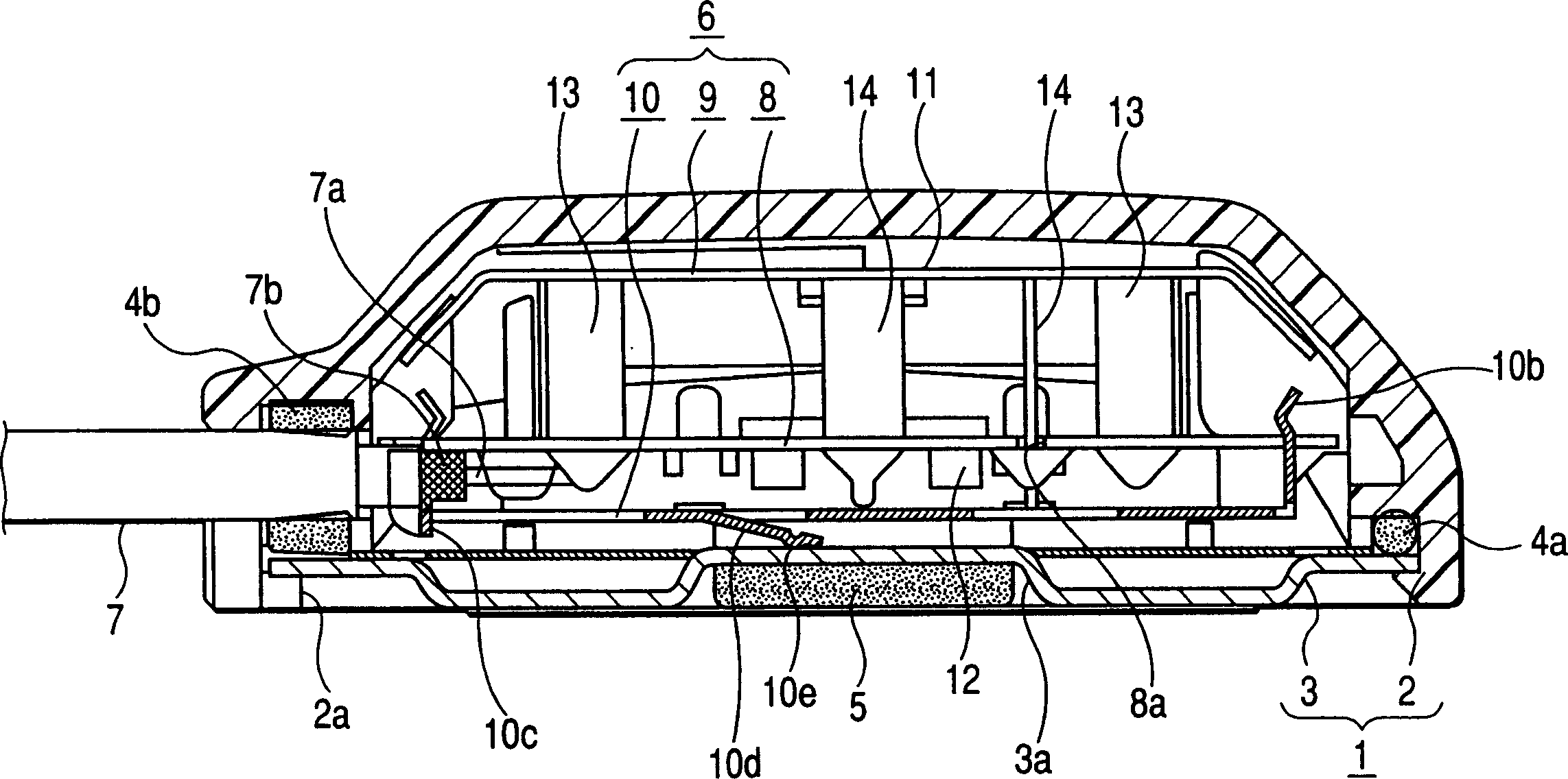
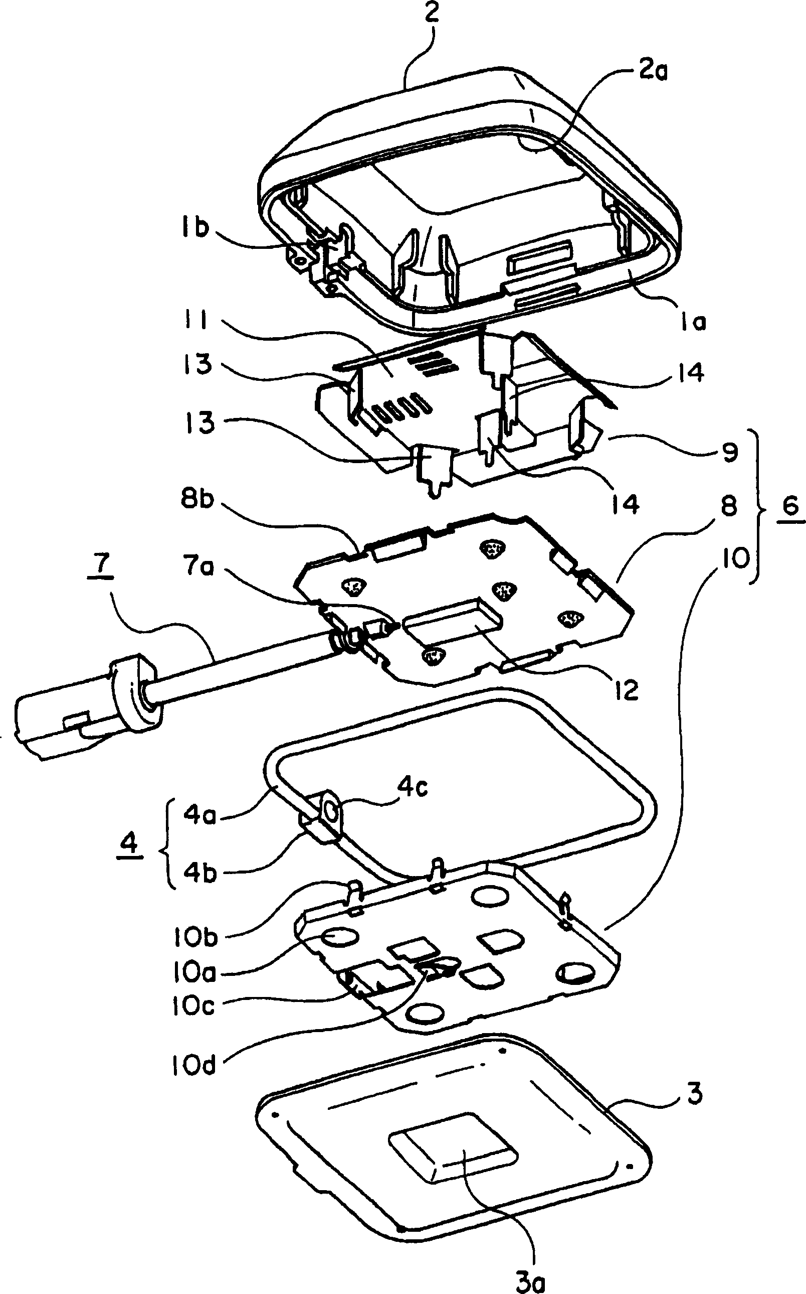
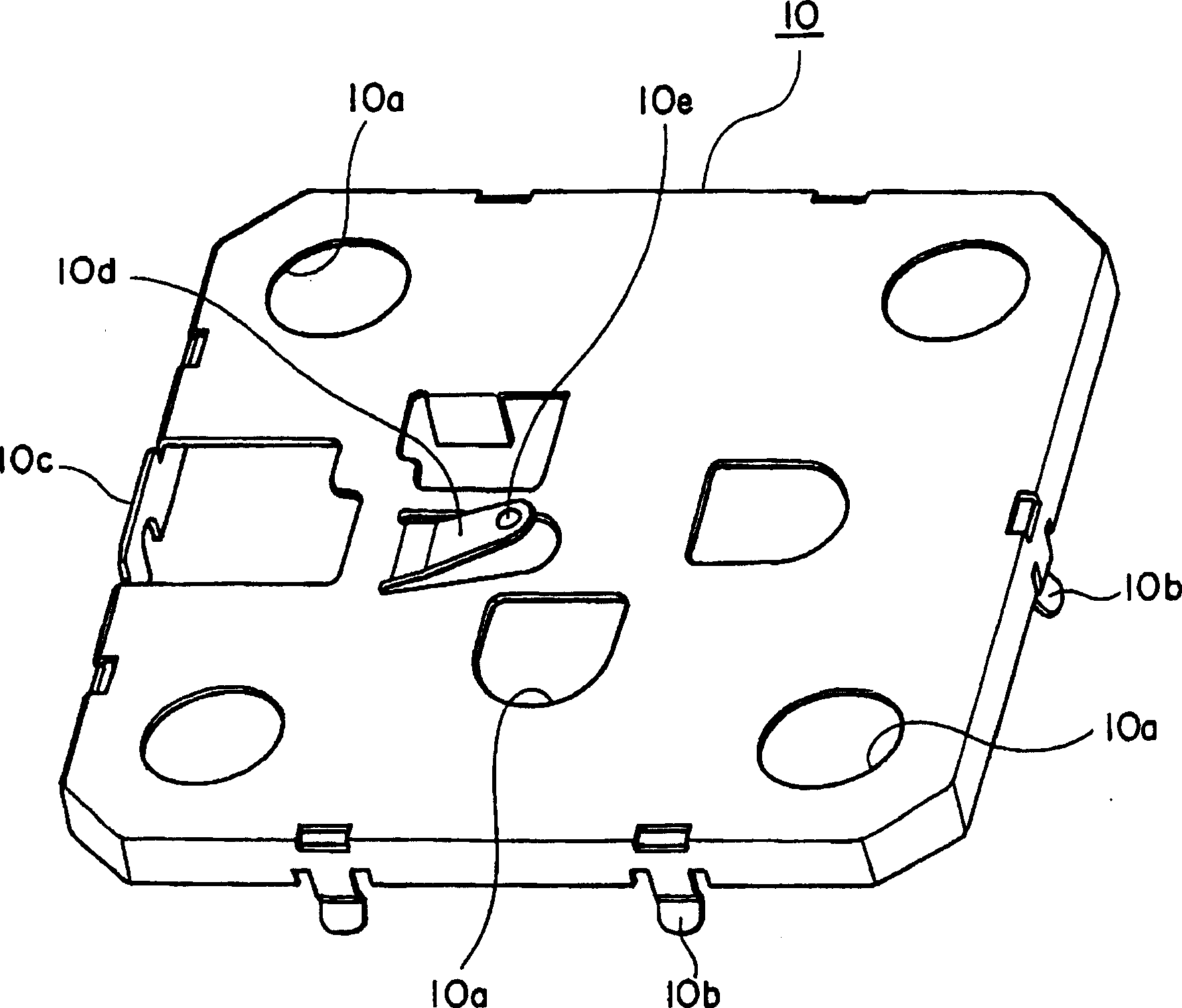
[0018] The embodiments of the invention will be described below with reference to the drawings. figure 1 Is a cross-sectional view of an antenna device according to an embodiment of the present invention, figure 2 Is an exploded perspective view of the antenna device, image 3 It is a perspective view of the shielding box used in the antenna device.

[0019] The antenna device shown in these figures mainly consists of a housing 1 formed by fitting the radome 2 and a metal cover 3, and a sealing member 4 mounted on the radome 2 and the fitting portion 1a of the metal cover 3, etc., mounted on The magnet 5 on the bottom side of the metal cover 3 and the antenna unit 6 housed in the internal space of the housing 1 are formed. The antenna unit 6 is connected to an external circuit (signal receiving circuit, etc.) not shown in the figure through a coaxial cable 7 connection. The antenna unit 6 is composed of a circuit board 8 with electronic circuit parts such as a low-noise amplifier...


PUM


Abstract

A case has a synthesized resin radome that houses and covers an antenna unit, and a metal cover that covers a bottom opening of the radome. A shield case and the metal cover facing each other are connected to each other by a tongue piece. The antenna unit includes a circuit board that has a wiring pattern and a semiconductor component mounted on a lower surface thereof, the shield case that covers the lower surface of the circuit board and is connected to an outer conductor of a coaxial cable, a radiating conductor plate that is substantially disposed in parallel with an upper surface of the circuit board by a predetermined gap, and feeding pieces that extend from the radiating conductor plate and are connected to the wiring pattern. The antenna unit in the case is connected to an external circuit through the coaxial cable.

Description

Technical field [0001] The present invention relates to a small antenna device suitable for use in vehicles, and more particularly to a unitized antenna body with a patch antenna structure and a circuit board equipped with a low-noise amplifier circuit, etc., and housed and held in a radome The antenna device. Background technique [0002] Such an antenna device is used as an antenna for ETC (Automatic Toll Collection System) or an antenna for GPS (Global Positioning System) installed in a moving body such as a vehicle, and the demand has been rapidly increasing in recent years. [0003] Conventionally, this type of antenna device is generally constructed by accommodating an antenna unit inside a housing composed of a pair of upper and lower radomes, and the antenna unit is connected to an external circuit through a coaxial cable. This antenna unit roughly consists of a circuit board with circuit patterns or semiconductor components arranged on the lower surface, an antenna body ...

Claims


Application Information

Patent Timeline
Patent Type & Authority Applications(China)
IPC IPC(8): H01Q1/32H01Q1/38H01Q13/08B60R16/02
CPCH01Q9/0407H01Q1/526H01Q1/42H01Q9/0428H01Q1/3291
Inventor 小池清志佐佐木和广
Owner ALPS ALPINE CO LTD
Why Eureka
Try Eureka