Inorganic salt blended organic electroluminescence light emitting display device

An electroluminescence display and inorganic salt technology, applied in the field of organic electroluminescence display devices, can solve the problems of unbalanced carrier injection, difficulty in injecting electrons, etc., so as to improve the efficiency of electron injection, save production costs, and increase the probability of Effect

Inactive Publication Date: 2006-08-23
SHAANXI UNIV OF SCI & TECH
View PDF0 Cites 8 Cited by
  • Summary
  • Abstract
  • Description
  • Claims
  • Application Information

AI Technical Summary

Problems solved by technology

In a typical organic electroluminescent device, from the cathode to the commonly used electron transport material Al

Method used


Image

  • Inorganic salt blended organic electroluminescence light emitting display device

Examples


Embodiment Construction

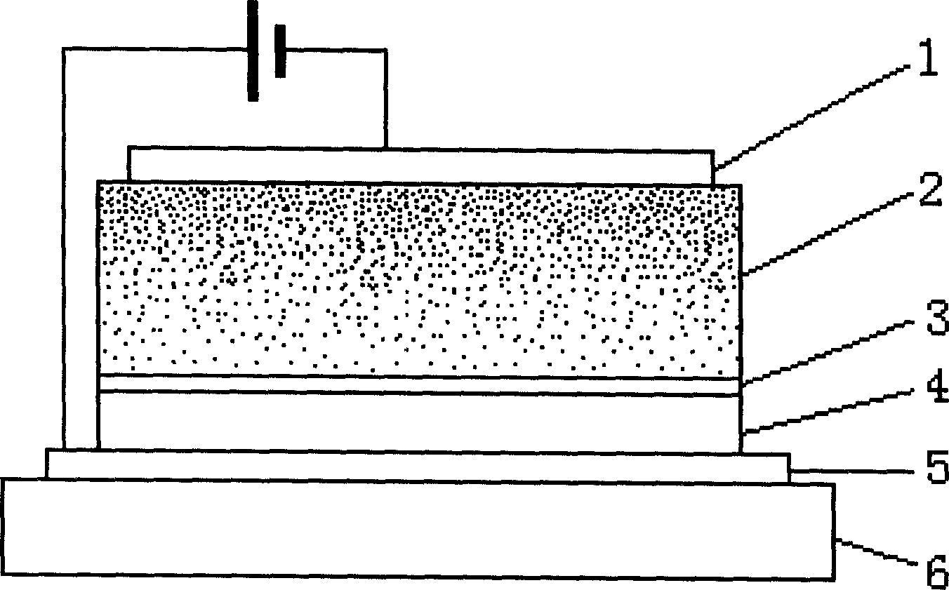
[0010] Below in conjunction with accompanying drawing, the utility model is described in further detail.

[0011] Referring to the accompanying drawings, the present invention includes a glass substrate 6 and an ITO conductive layer 5, a hole transport layer 4, a lower light-emitting layer 3, an upper light-emitting layer 2 and a metal cathode 1 that are sequentially arranged on the upper surface of the glass substrate 6 from bottom to top, wherein , the ITO conductive layer 5 and the metal cathode 1 are respectively connected to the positive and negative electrodes of the DC voltage, the upper light-emitting layer 2 is doped with lithium fluoride LiF or lithium bromide LiBr inorganic salt material, and the inorganic salt material near the metal cathode 1 is connected to the luminescent The maximum molar doping ratio of the material is less than 80%, and the doping gradient decreases downward according to 2% / nanometer.

[0012] In organic electroluminescent display devices, or...


PUM


Abstract

An inorganic salt doping type organic electroluminescent display device includes glass substrate, ITO conducting layer in turn set on glass substrate upper surface, hole transmission layer, lower luminescent layer, upper luminescent layer and metallic cathode, wherein ITO metallic cathode and metallic cathode respectively connected with dc voltage positive and negative electrode, upper luminescent layer doped with inorganic salt material, the maximal doped proportion of inorganic salt material and luminescent material less than 80 per cent down descending according to 2 per cent/nano doping gradient. Present invention leads inorganic salt in luminescent layer of organic electroluminescence device, solving low carrier mobility problem, raising electron injection efficiency, greatly increasing electronic and hole compound luminous probability, improving OLED device luminous efficiency, luminescence brightness and service life, saving cost and reducing technology hardness.

Description

technical field [0001] The invention belongs to an organic electroluminescent display device (OLED) in the field of flat panel display, and in particular relates to an inorganic salt doped organic electroluminescent display device. Background technique [0002] In 1987, since Tang, an American Kodak company, first reported a high-efficiency, high-brightness organic electroluminescent thin film device with a double-layer structure, it has attracted great attention because of its low driving voltage, high luminous brightness, rich colors and It has become a research hotspot in the field of flat panel display due to its advantages such as simple process and large-area flat panel display. Luminous efficiency and luminous lifetime are two key issues for the practical application of organic electroluminescent devices, but there is a theoretical limit to the electroluminescent efficiency. In order to be able to be used in situations where strong light is required, such as lighting...

Claims


Application Information

Patent Timeline
IPC IPC(8): H01L51/50H01L51/54H05B33/20
Inventor 王秀峰牟强李新贝张方辉靳宝安马颖
Owner SHAANXI UNIV OF SCI & TECH
Why Eureka
Try Eureka