Binding type thermal-insulation composite wall with support

A thermal insulation composite and bundled technology, applied in the direction of walls, building components, covering/lining, etc., can solve the problems of adding thermal bridges, complicated treatment of steel support thermal bridges, troublesome connection of steel supports and vertical steel bars, etc.

Inactive Publication Date: 2006-09-06
吴淑环
View PDF1 Cites 18 Cited by
  • Summary
  • Abstract
  • Description
  • Claims
  • Application Information

AI Technical Summary

Problems solved by technology

The current various wall insulation technologies have the following problems: 1. The contradiction between safety and insulation has not been solved from the perspective of optimization, that is, the wall insulation with good safety is not good; the wall with good insulation is not safe , manifested in unsafe structure or difficult construction quality control, and unsafe fire prevention. The main reason is to solve the connection between the insulation layer and the wall from the material, without relying on structural means or simple structural means
Also, because many blocks have their own thermal bridges, these factors have a great impact on building energy saving and high cost, and it is impossible to achieve a low heat transfer coefficient of the wall, especially the lower the heat transfer coefficient of the wall, the greater the impact on the cost and wall thickness
Some use steel anchor bolts to connect with the base wall, but this structural connection is too simple to meet the requirements of large horizontal wind pressure and large horizontal earthquake action on the external wall. When the wall is thickly decorated, the rigidity of steel anchor bolts is too small, it is difficult to meet the safety requirements, and it is even more difficult to anchor reliably with various masonry, such as brick masonry and lightweight filled masonry, and these insulation technologies are used for connecting steel The density of anchor bolts is high, such as the benzene plate of the abdominal wire penetrating steel wire mesh frame, and the steel that penetrates the benzene plate reaches 7.4/m 2 , increase heat transfer, use non-corrosion or low-corrosion anchor bolts in the insulation layer, which are easy to corrode and affect durability
2. In the heating area with 50% energy saving, when the outer protective layer is d

Method used


Image

  • Binding type thermal-insulation composite wall with support
  • Binding type thermal-insulation composite wall with support
  • Binding type thermal-insulation composite wall with support

Examples


specific Embodiment approach 1

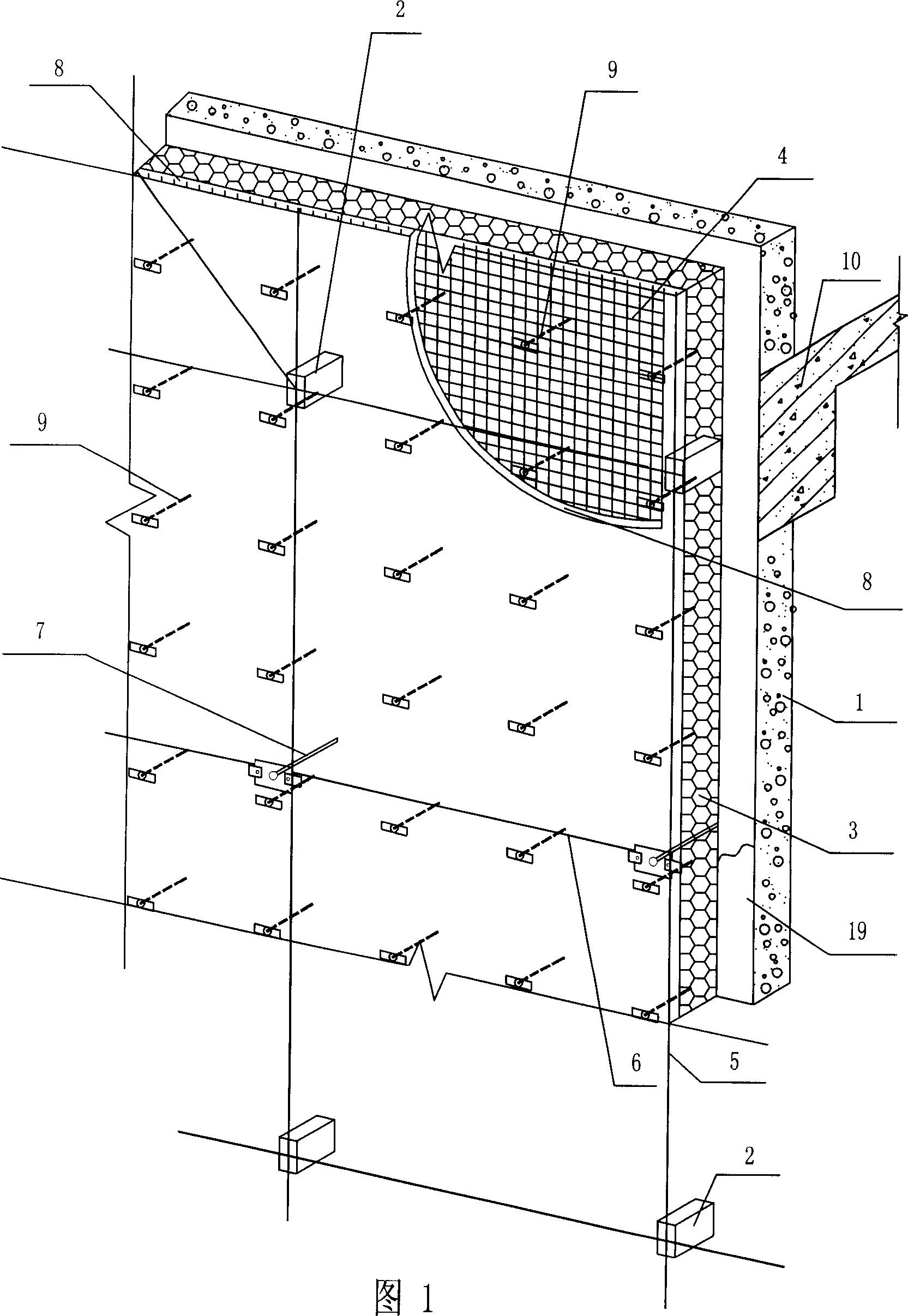
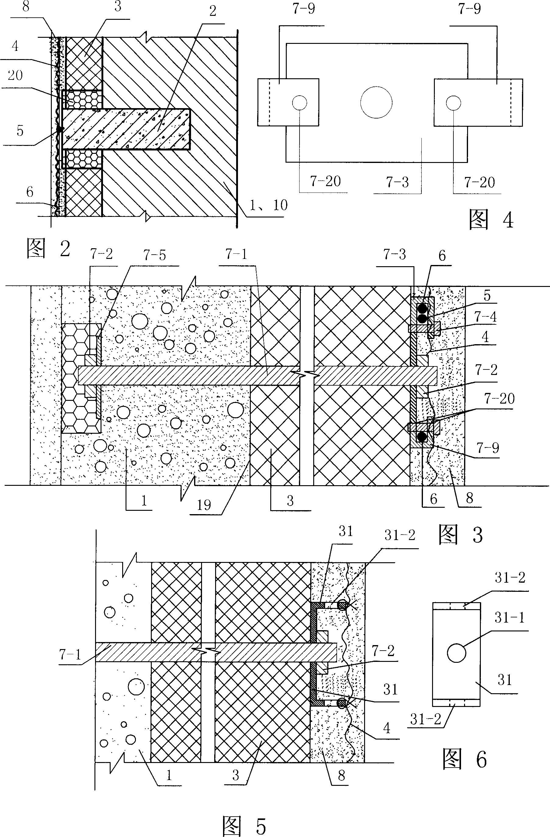
[0005] Specific embodiment one: (see Fig. 1, Fig. 2, Figure 9 , Fig. 10) the present embodiment consists of base wall body 1, concrete cantilever beam support member 2, insulation layer 3, metal mesh 4, vertical steel bar 5, internal and external pull joints 7, outer protective layer 8, plastic expansion nail 9 and Concrete components 10 of the main structure of the building consist of concrete ring beams, concrete girders, concrete columns, concrete walls, concrete lintels, concrete foundations, concrete balcony slabs, and upper and lower floors of multi-layer masonry structures. Concrete pilasters or concrete window sills on the window side connected to the surface concrete, and the inner end of the concrete cantilever beam support 2 is fixed on the inside or outside of the concrete member 10 of the main building structure and fixed with steel pieces, or fixed on the load-bearing masonry In the base wall 1, the inner end of the inner and outer pull connectors 7 is fixed in ...

specific Embodiment approach 2

[0007]Specific embodiment two (referring to Fig. 11, Fig. 12) the plastic expansion nail 9 of this embodiment is made up of plastic rod cover 9-1, plastic rod core 9-2 and the 3rd steel spacer 30, and the 3rd steel spacer 30 is set On the outer end 9-3 of the plastic rod core 9-2, the plastic rod core 9-2 passes through the hole 30-1 of the third steel gasket 30 and is driven into the plastic rod cover 9-1, and the insulation layer 3 is used The plastic expansion nail 9 is fixed, and is fixed with the metal mesh 4 with the hole 30-2 on the third steel spacer 30, and the third steel spacer 30 can also be replaced by the second steel spacer 31, and the second steel spacer 31 is located in the plastic Between the outer end 9-3 of the rod core 9-2 and the insulation layer 3, the metal mesh 4 is connected with the plastic expansion nail 9 through the hole 31-2 on the third steel gasket 31. But the third steel gasket 30 can reduce the vibration when the metal mesh 4 is plastered tha...

specific Embodiment approach 3

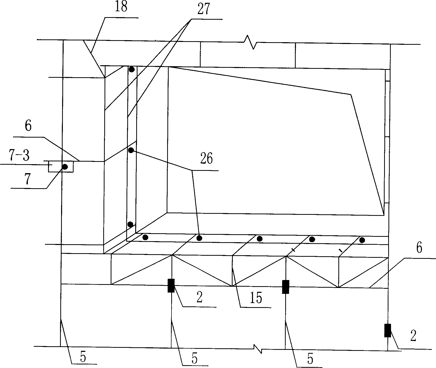
[0008] Specific embodiment three (referring to Fig. 1~Fig. 3, Figure 7 ~ Fig. 10): The difference between this embodiment and the specific embodiment one is that a horizontal transverse steel bar 6 is added in the outer protective layer 8, and the two ends of the horizontal transverse steel bar 6 are welded to the embedded steel plate at the outer end of the concrete cantilever beam support 2 Or be fixed on the outer end of the inner and outer pull connector 7. The setting of horizontal and horizontal steel bars can increase the binding and fixing points of the metal mesh. The horizontal horizontal steel bars and the vertical steel bars together constitute the four-sided constraints of the outer protective layer, which is more conducive to increasing the rigidity of the outer protective layer and limiting the deformation of the outer protective layer. The distance between cantilever beam supports is convenient for construction and reduces the thermal bridge of concrete cantile...


PUM


Abstract

The invention relates to a bound thermal-insulation composite wall with supports, which provides an external thermal-insulation composite wall of building, to overcome the defects of present technique. Wherein, the concrete hanging beam support (2), the internal outwards-drawing connector (7), and the inner end of plastic expansion nail (9) are fixed inside the main construct concrete (10) or basic wall (1); the concrete hanging beam support (2) and the outer end of inner outwards-drawing connector (7) are inside the outer protective layer (8) to connect the vertical steel bar (5); the outer side of basic wall (1) has a thermal-insulated layer (3) fixed via plastic expansion nail (9); the outer side of thermal-insulated layer (3) has a vertical steel bar (5); the outer or inner side of vertical steel bar (5) has a metallic network (4) which is connected to the vertical steel bar (5); the outer side of thermal-insulated layer (3) has a outer protective layer (8) made from cement sand pulp or pea stone concrete. The invention has the advantages that safety, long service life, better thermal insulation and flameproof.

Description

technical field [0001] The invention relates to an external thermal insulation composite wall body of a building. Background technique [0002] The world's energy is becoming more and more tense. Building energy conservation is an important issue for the sustainable development of human society. Wall insulation and energy-saving technology is an important part of building energy conservation. The current various wall insulation technologies have the following problems: 1. The contradiction between safety and insulation has not been solved from the perspective of optimization, that is, the wall insulation with good safety is not good; the wall with good insulation is not safe , manifested in unsafe structure or difficult construction quality control, and unsafe fire prevention. The main reason is to solve the connection between the insulation layer and the wall from the material, without relying on structural means or simple structural means. For example, in the heating area...

Claims


Application Information

Patent Timeline
IPC IPC(8): E04B2/00E04B1/00E04F13/21
Inventor 吴淑环
Owner 吴淑环
Why Eureka
Try Eureka