Laser cell microoperation control method and device for metal particle

A technology of metal particles and control devices, which is applied in the laser micro field to achieve the effect of rapid prototyping and manufacturing

Inactive Publication Date: 2006-09-13
BEIJING UNIV OF TECH
View PDF0 Cites 14 Cited by
  • Summary
  • Abstract
  • Description
  • Claims
  • Application Information

AI Technical Summary

Problems solved by technology

[0005] The purpose of the present invention is to solve the defect that the traditional laser optical tweezers control method cannot realize the direct control of metal particles, make full use of the property that metal particles have a high reflectivity to laser light, and propose a laser optical tweezers for metal particles Micro-manipulation method, using this method can achieve direct manipulation of metal particles

Method used


Image

  • Laser cell microoperation control method and device for metal particle
  • Laser cell microoperation control method and device for metal particle

Examples


Embodiment Construction

[0023] Embodiments of the present invention will be described in detail below in conjunction with the accompanying drawings.

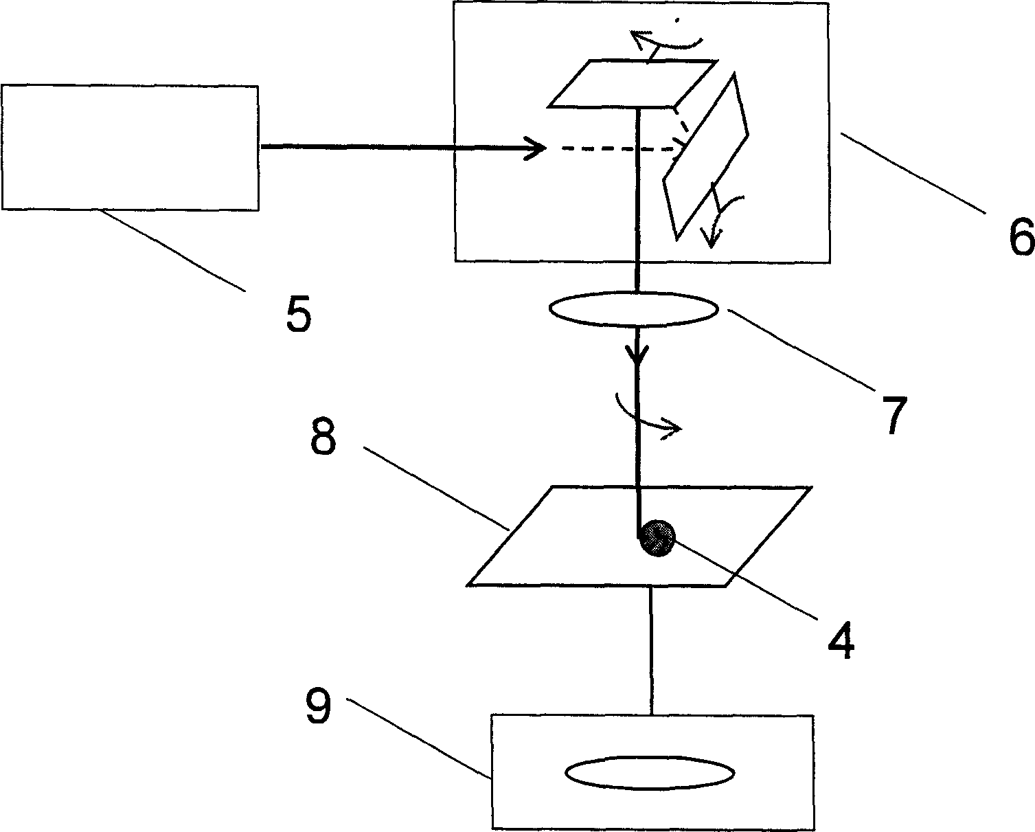
[0024] figure 2 It is a schematic diagram of the composition of the laser optical tweezers manipulation device of the present invention. The control device designed according to the method of the present invention includes: a laser 5 , a two-dimensional scanning galvanometer system 6 , a focusing mirror 7 , a two-dimensional motion platform 8 , and a microscopic observation system 9 .

[0025] Among them, the function of the laser 5 is to emit the laser light source, the function of the focusing mirror 7 is to converge the laser beam, the function of the two-dimensional scanning galvanometer system 6 is to control the scanning direction of the laser beam, and the function of the two-dimensional motion platform 8 is to place Metal particles and control the direction of movement of the metal particles, the role of the microscopic observation system 9 i...


PUM


Abstract

A method for manipulating the laser tweezers of metallic micro-particles features that a 2D scanning polarizer system is used to control the circular scanning of laser beam around metallic micro-particles, and the action force of laser beam to each metallic micro-particle points to the curvature center of scanning trace, so gathering the metallic micro-particles in the center. Its apparatus is composed of laser device, focusing lens, 2D moving platform, microscopic observing system, and 2D scanning polarizer system.

Description

technical field [0001] The invention belongs to the field of laser microtechnology, and according to the basic principle of laser photon dynamics, utilizes the interaction between laser photons and objects to realize a light manipulation method. Background technique [0002] Since the invention of laser optical tweezers by Ashkin·A in 1986, laser optical tweezers have developed rapidly and become an effective means of capturing and manipulating micron-scale and biological cells. [0003] The traditional laser optical tweezers technology is based on the principle of laser photon dynamics. By focusing the micro-laser beam near the transparent particle, a strong gradient force is generated near the focusing center to form an "optical trap". The binding force of the trap to the transparent particles in it is used to realize the capture and manipulation of particles by laser optical tweezers, which is widely used in the field of biological research at the cell and molecular level...

Claims


Application Information

Patent Timeline
Patent Type & Authority Applications(China)
IPC IPC(8): B81B7/02G02F1/01
Inventor 陈继民孙大庆宗小军
Owner BEIJING UNIV OF TECH
Why Eureka
Try Eureka