Clutch type screw press

A screw press, clutch technology, applied in the direction of presses, punching machines, manufacturing tools, etc., can solve the problems of consuming flywheel energy and affecting the striking force of the slider, avoiding additional consumption, large striking force, and good process performance. Effect

Inactive Publication Date: 2006-09-27
韩宝林
View PDF1 Cites 4 Cited by
  • Summary
  • Abstract
  • Description
  • Claims
  • Application Information

AI Technical Summary

Problems solved by technology

However, during the working stroke of the slider, the downward speed is very high. Affected by the oil discharge process of the oil cylinder, the slider is subjected to relatively large resistance, which consumes the energy of the flywheel and affects the striking force of the slider.

Method used


Image

  • Clutch type screw press
  • Clutch type screw press
  • Clutch type screw press

Examples


Embodiment Construction

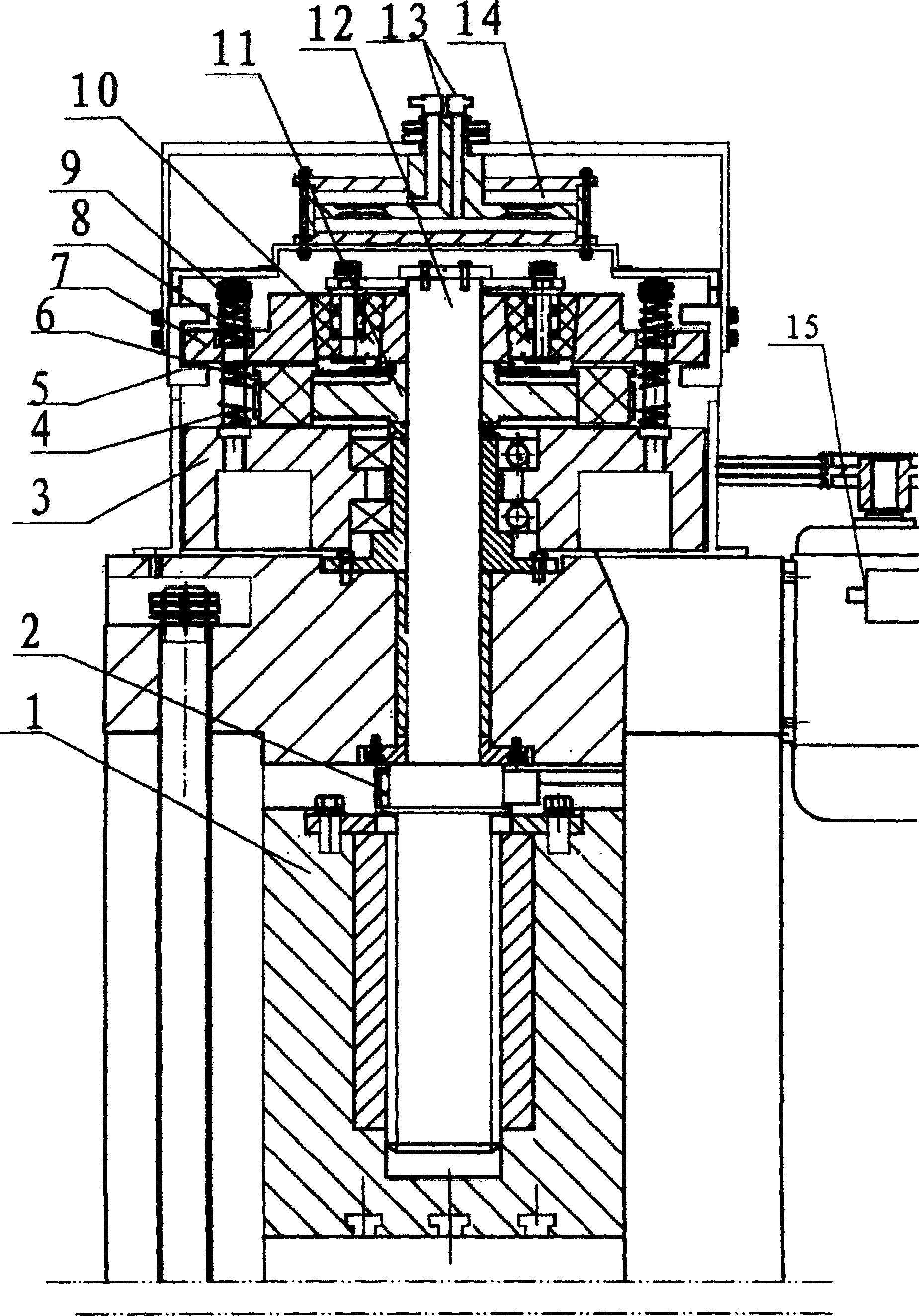
[0019] exist figure 1 Among them, a screw rod 12 is installed at the center of the frame, the bottom of the screw rod 12 is connected with a brake device 2 and a slider 1, and a nut is installed between the slider 1 and the screw rod 12. The flywheel 3 is connected with the motor 15 of the electric control system through a belt. The flywheel 3 and the clutch are sequentially connected to the top of the screw rod 12 from bottom to top. The clutch is connected with a cylinder 14 driven by compressed air.

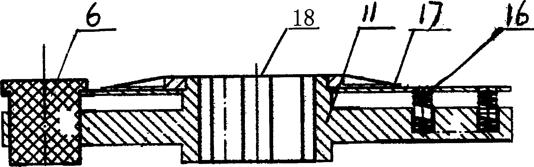
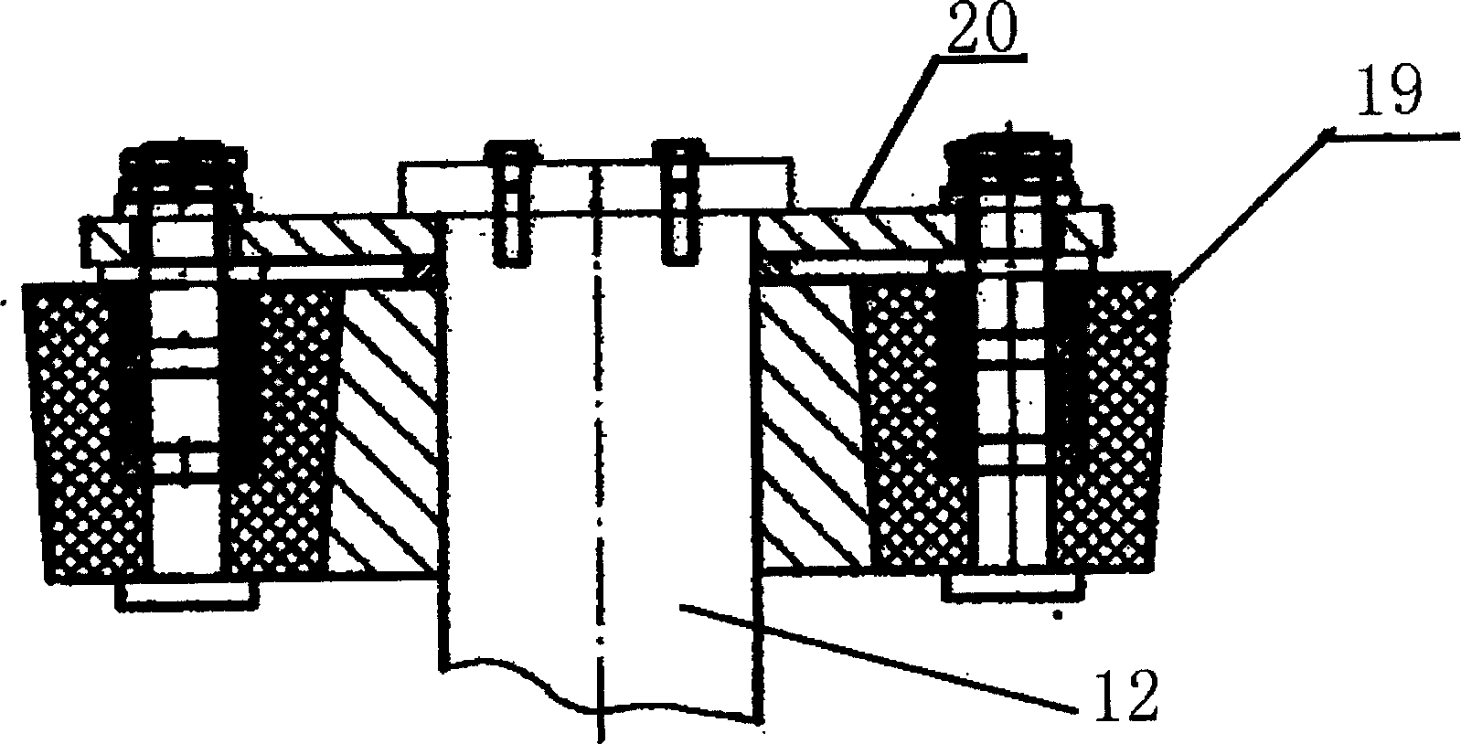
[0020] The power disc 11 and the friction wheel train 10 of the clutch are sequentially connected to the top of the screw rod 12 from bottom to top. Bearing is housed between flywheel 3 and screw rod 12. The inner side of the pressing plate 7 is provided with an inclined surface, which is sleeved on the outside of the friction wheel train 10 . The lower end of the guide post 9 with the upper spring 8 and the lower spring 4 is fixedly connected with the flywheel 3, and the ...


PUM


Abstract

The clutch type screw press includes a frame, a sliding block, a flywheel and a motor. On the frame, there are screw in the center, brake and sliding block connected to the lower part of the screw, flywheel and clutch, comprising a power disc and a friction wheel train, connected to the upper part of the screw, compressed air driven cylinder connected to the clutch, pressing board around the lower part of the friction wheel train, guide post with spring and with upper end fixed to the flywheel and lower end connected movably to the pressing board, and operating block around the pressing board and connected to the cylinder. The clutch type screw press has compressed air as operating power of the clutch, less pressure releasing links, fast pressure release, simple structure, great impact force and other advantages, and may be used in pressure formation of metal material in different industry.

Description

technical field [0001] The invention relates to a clutch type screw press machine used for pressure forming processing of metal materials. Background technique [0002] Chinese patent 200310105468.9 specification discloses a clutch type screw press. The press includes a pulley, a flywheel, a slider, a return system, a clutch, a pressing system, a pressure relief system, a hydraulic system and an electrical circuit system. [0003] The pressure relief system of this press adopts an electromagnetic hydraulic sensor, and the oil pressure in the compression cylinder increases with the increase of the process force. When the oil pressure reaches the set value of the electromagnet current, the electromagnetic hydraulic sensor acts, and the pressure is relieved through the pilot valve and the main valve. When unloading, multiple control valves in the hydraulic system need to be opened in sequence, the opening response time is long, unloading lags behind, a...

Claims


Application Information

Patent Timeline
IPC IPC(8): B30B1/18
CPCB30B1/188
Inventor 韩宝林
Owner 韩宝林
Why Eureka
Try Eureka