Mechanism for burying waste residue in reservoir bottom

A waste residue and reservoir technology, applied in large-capacity bulk material storage, water conservancy projects, marine engineering and other directions to achieve the effect of saving project investment, reducing a large number of occupations, and reducing site area

Active Publication Date: 2006-09-27
POWERCHINA HUADONG ENG COPORATION LTD
View PDF0 Cites 5 Cited by
  • Summary
  • Abstract
  • Description
  • Claims
  • Application Information

AI Technical Summary

Problems solved by technology

[0003] The technical problem to be solved by the present invention is: combining the characteristics of the project to provide a structure for burying waste residue at the bottom of the reservoir, using this structure can reduce the large occupation of land resources and the adverse impact on the environment, and at the same time reduce the difficulty of initial water storage in the power station , reduce engineering investment

Method used


Image

  • Mechanism for burying waste residue in reservoir bottom
  • Mechanism for burying waste residue in reservoir bottom
  • Mechanism for burying waste residue in reservoir bottom

Examples


Embodiment Construction

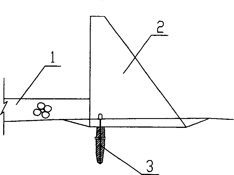
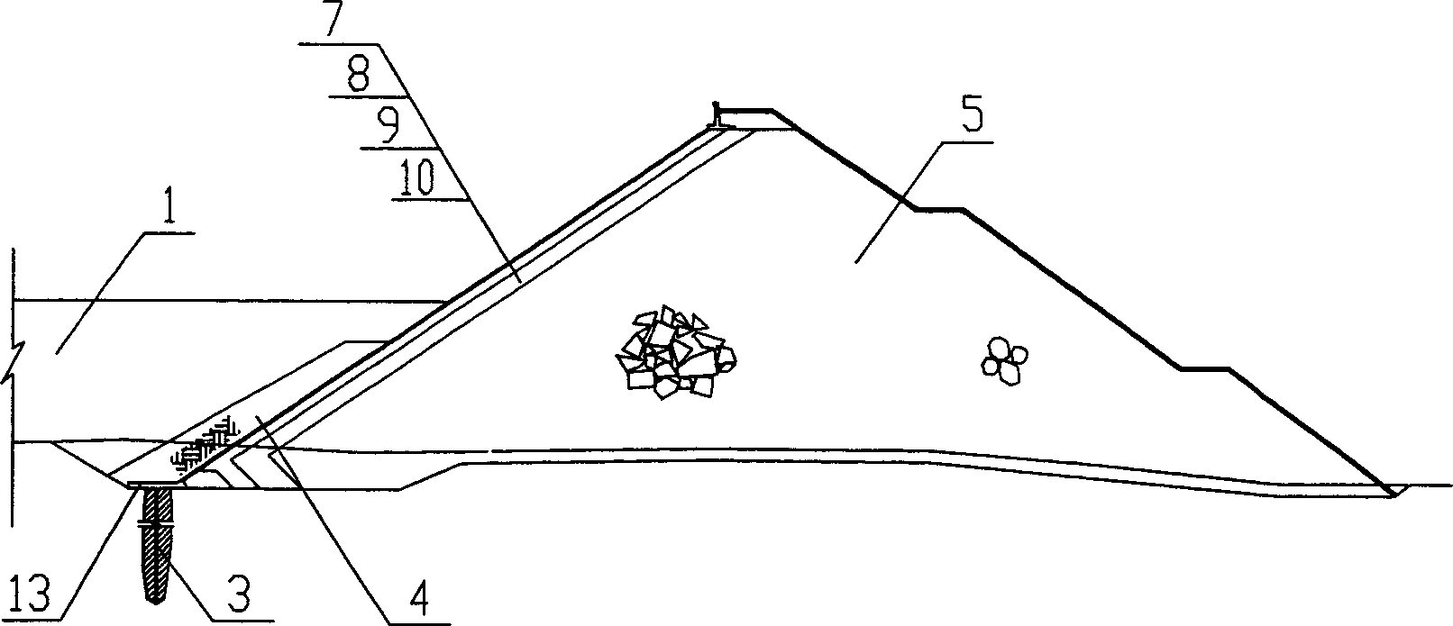
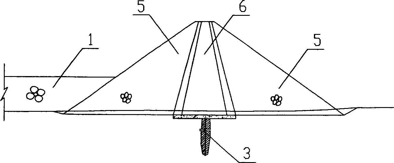
[0023] In the present invention, a large amount of waste soil and rock produced during the construction of the power station is called reservoir bottom slag 1, and the humus soil layer on the surface is removed, rolled and buried in layers in the dead storage capacity of the reservoir in an idle state.

[0024] figure 1 , figure 2 , image 3 What is shown is the implementation plan in which the water is only blocked by the dam, and the surface layer anti-seepage facilities (protective layer) are not provided on the bank and the bottom of the reservoir. figure 1 represents the concrete gravity dam 2, figure 2 is a concrete face dam, image 3 It is a rockfill dam with a clay core wall 6 . In this scheme, the surface of the slag filling 1 at the bottom of the reservoir is horizontal, and the water inlet and outlet 14 near the forebay 15 are slope-like, and the slag slope angle is smaller than the underwater repose angle of the slag filling, which is the maximum angle to ach...


PUM


Abstract

The invention relates to a reservoir bottom slag-embedding structure, which can reduce occupied area and reduce the cost without polluting the environment. It is characterized in that: embedding slag into the dead reservoir at the water accumulation side of reservoir dam. The invention can be used in small reservoir with small flow section.

Description

technical field [0001] The invention relates to a structure for filling waste slag at the bottom of a reservoir. It is suitable for power station reservoirs with small drainage areas, such as upper and lower reservoirs of pumped storage power stations, water supply reservoirs, etc. Background technique [0002] In the construction of a power station, a large amount of waste earth and stone will inevitably be produced. Generally speaking, the volume of waste earth and stone in a large-scale project is often as many as several million, or even tens of millions of cubic meters. For these soil and rock waste materials, the usual way to deal with them is to select a special site near the project area to store the waste slag. The problems in this treatment method are: 1) The construction of the waste slag field and the road to the waste slag field It will occupy a large amount of land resources and cause damage to the environmental vegetation of the waste dump site; 2) The waste ...

Claims


Application Information

Patent Timeline
Patent Type & Authority Applications(China)
IPC IPC(8): E02B7/00E02B8/00E04H7/02
Inventor 张春生姜忠见
Owner POWERCHINA HUADONG ENG COPORATION LTD
Why Eureka
Try Eureka