Check patentability & draft patents in minutes with Patsnap Eureka AI!

Automatic compression release mechanism including feature to prevent unintentional disablement during engine shutdown

A technology of components and recesses, applied in the direction of engine components, machines/engines, valve devices, etc., can solve problems such as failure of starting, difficulty in restarting the engine, etc.

Inactive Publication Date: 2006-09-27
KOHLER CO
View PDF0 Cites 1 Cited by
  • Summary
  • Abstract
  • Description
  • Claims
  • Application Information

AI Technical Summary

Problems solved by technology

Consequently, this automatic decompression device becomes disabled for subsequent starts, thus making it difficult to restart the engine due to the high compression force

Method used


Image

  • Automatic compression release mechanism including feature to prevent unintentional disablement during engine shutdown
  • Automatic compression release mechanism including feature to prevent unintentional disablement during engine shutdown
  • Automatic compression release mechanism including feature to prevent unintentional disablement during engine shutdown

Examples


Embodiment Construction

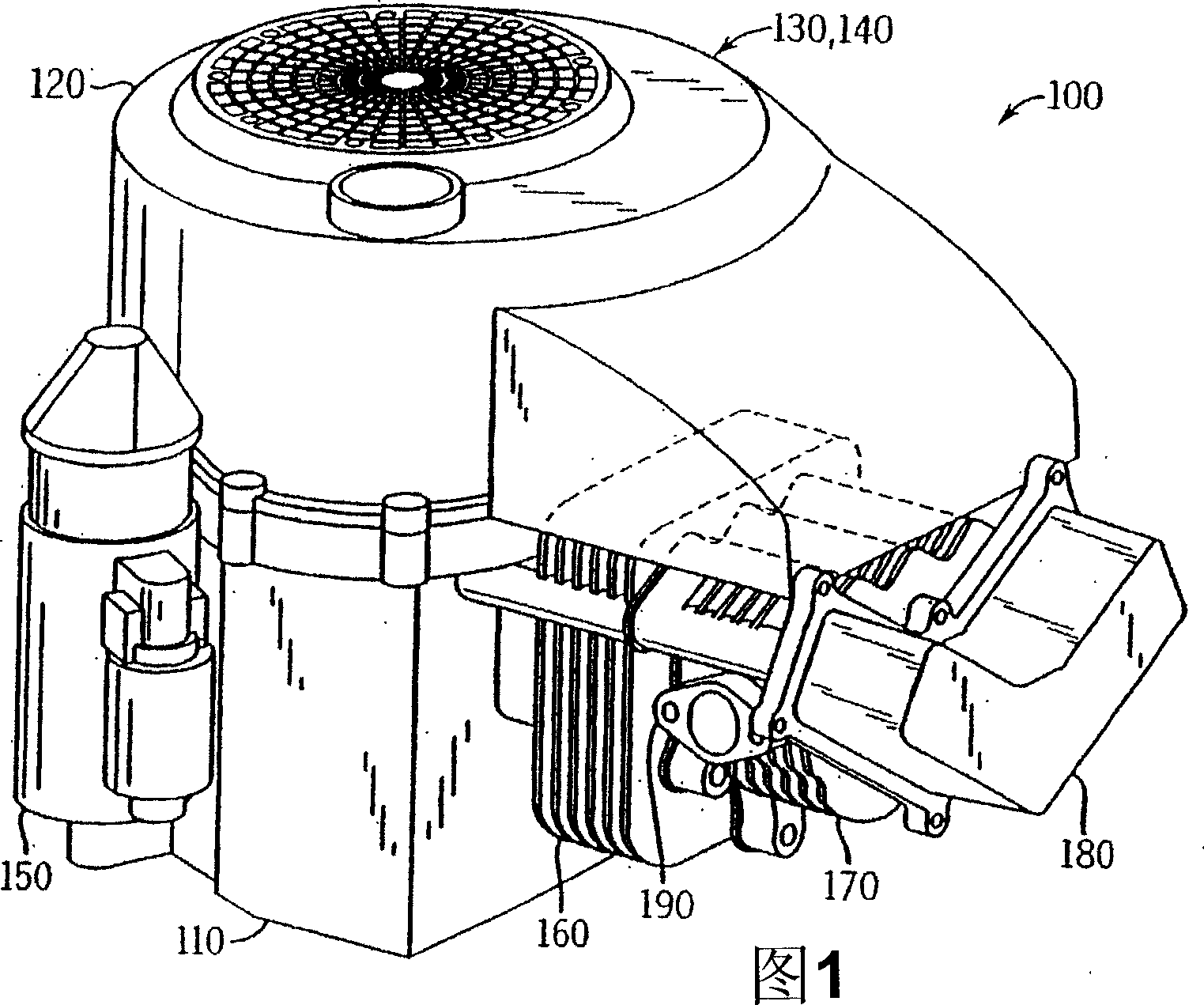
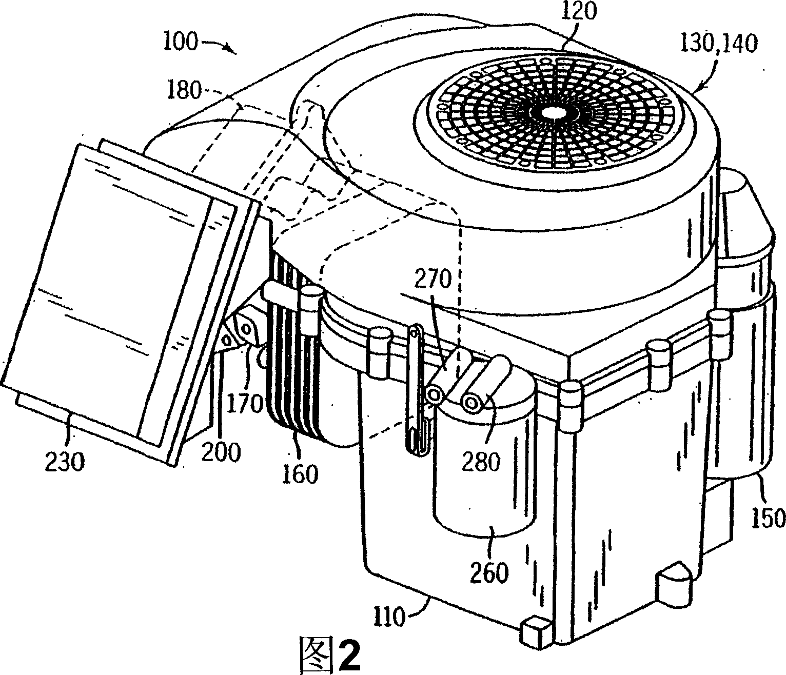
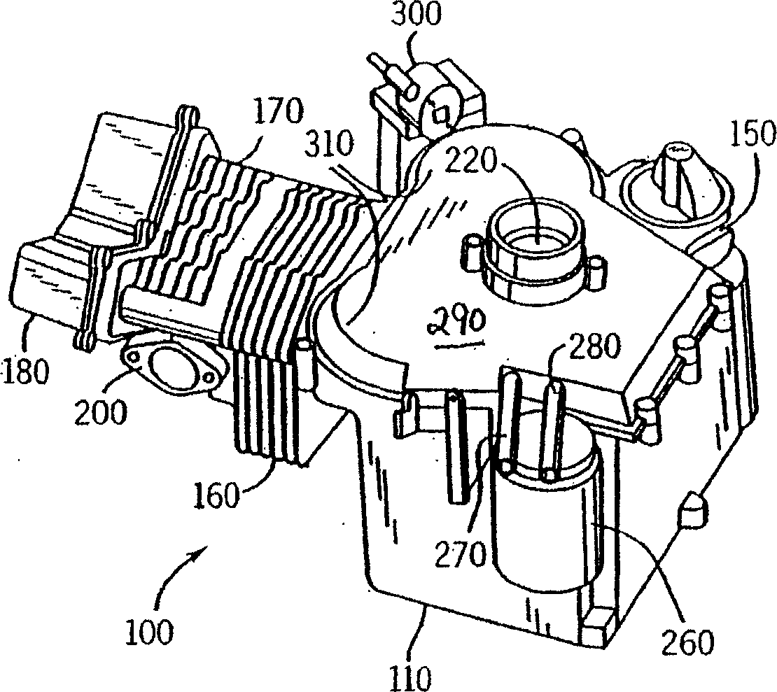
[0024] 1 and 2, a single cylinder, four-stroke internal combustion engine 100 includes a crankcase 110, and a blower housing 120 with a fan 130 and a flywheel 140 therein. The engine 100 also includes a starter 150 , a cylinder 160 , a cylinder head 170 and a rocker cover 180 . The exhaust port 190 shown in FIG. 1 and the intake port 200 shown in FIG. 2 are mounted on the cylinder head 170 . During operation of engine 100 , piston 210 (see FIG. 7 ) reciprocates within cylinder 160 toward and away from cylinder head 170 , as is known in the art. Movement of piston 210 in turn causes rotation of crankshaft 220 (see FIG. 7 ), as well as rotation of fan 130 and flywheel 140 connected to the crankcase. The rotation of the fan 130 cools the engine, and the rotation of the flywheel 140 maintains a relatively constant rotational momentum.

[0025] Referring now to FIG. 2 , the engine 100 further includes an air cleaner 230 connected to the intake port 200 to filter air required by t...


PUM


Abstract

An automatic compression release mechanism for in an internal combustion engine, includes a camshaft assembly including a cam gear, a cam lobe with a notch positioned along a first side of the gear, a tube passing through the cam gear and aligned with the notch, and a support on a second side of the cam gear. An actuator assembly includes a contoured shaft that extends through the tube and resides in the notch. The actuator assembly is rotatable between two operating orientations and a step formed in the surface of the notch prevents the actuator from becoming disabled during engine shut down.

Description

technical field [0001] This invention relates to internal combustion engines, and more particularly, to automatic compression release devices for use in internal combustion engines. Background technique [0002] Automatic pressure relief devices are used in internal combustion engines to provide improved engine performance at various engine speeds. The device typically includes components actuated based on engine speed, which alters the characteristics of the outer surface of the cam lobe, along which mating valvetrain components drive the engine exhaust and / or intake valves . When the engine starts, a protrusion is created on the cam lobe, causing the exhaust valve to open slightly during the engine's compression stroke. The decompression caused by the "low speed orientation" reduces the effort to start the engine. However, when the engine speed is high, such as during normal operation or standby, the protrusion is eliminated, allowing the exhaust valve to remain closed ...

Claims


Application Information

Patent Timeline
IPC IPC(8): F01L13/08
Inventor T·M·罗特P·L·贝滕豪森T·E·韦尔曼S·X·陈H·云
Owner KOHLER CO
Features
  • R&D
  • Intellectual Property
  • Life Sciences
  • Materials
  • Tech Scout
  • Unparalleled Data Quality
  • Higher Quality Content
  • 60% Fewer Hallucinations
Learn More