Light detecting element and control method of light detecting element

一种光探测、元件的技术,应用在光探测元件领域,能够解决响应速度减少、花费读出时间等问题

Inactive Publication Date: 2006-09-27
MATSUSHITA DENKO KK
View PDF1 Cites 14 Cited by
  • Summary
  • Abstract
  • Description
  • Claims
  • Application Information

AI Technical Summary

Problems solved by technology

That is, since it takes 2 frames of readout time until the detection result is obtained, the response speed is reduced by this time

Method used


Image

  • Light detecting element and control method of light detecting element
  • Light detecting element and control method of light detecting element
  • Light detecting element and control method of light detecting element

Examples


Embodiment Construction

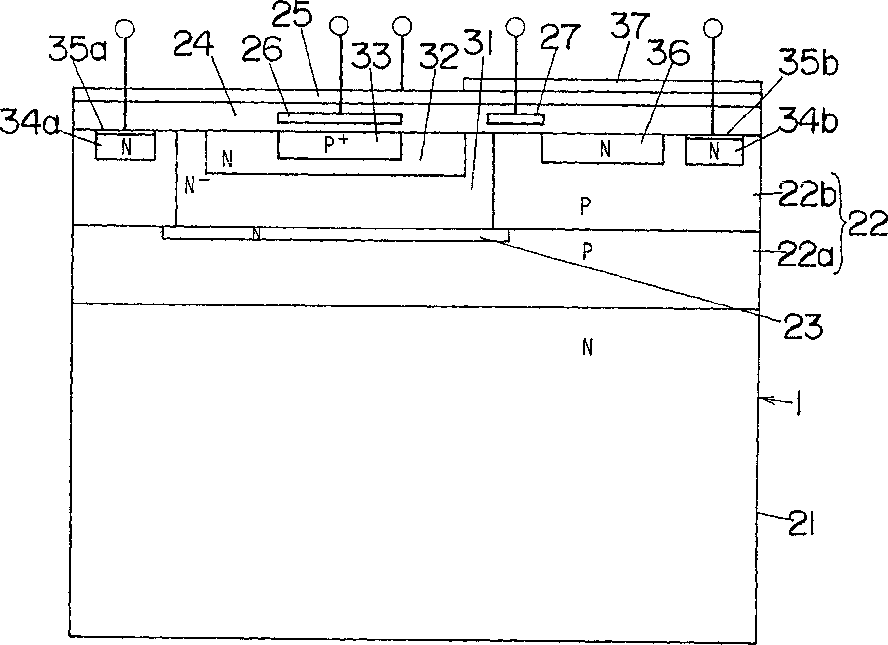
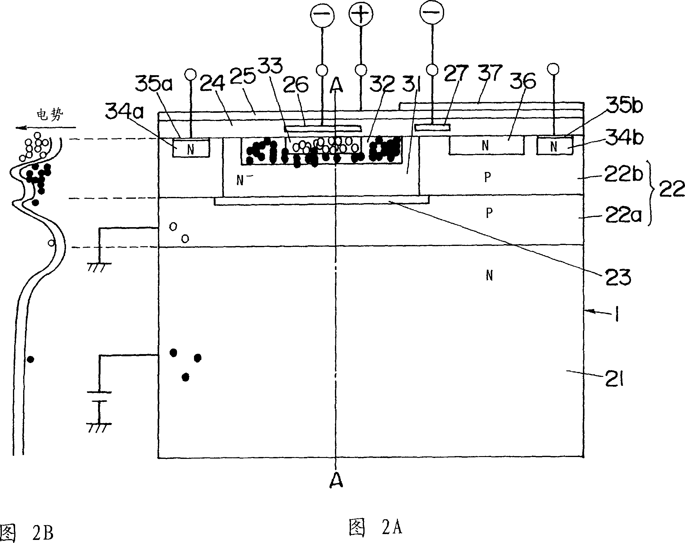
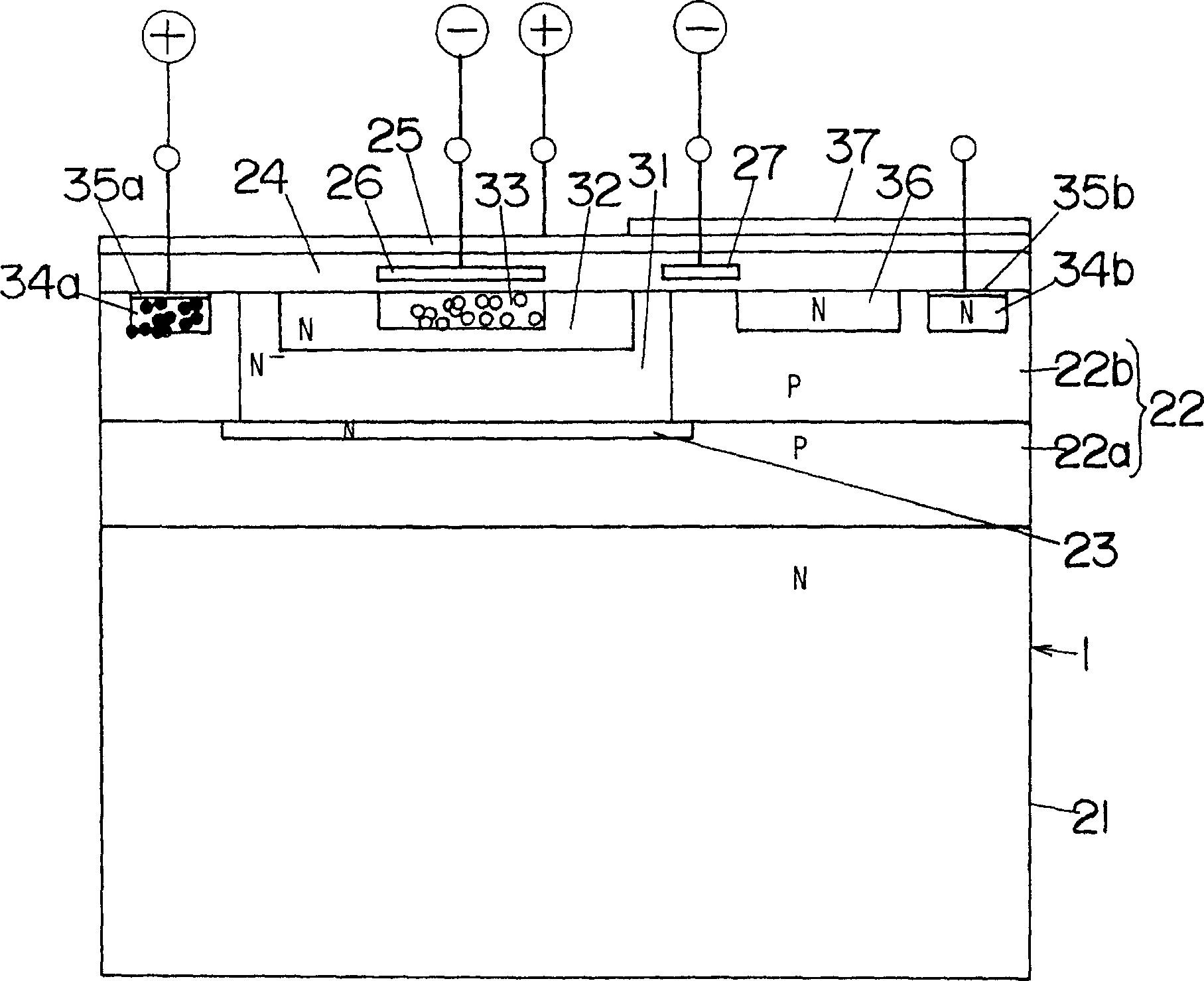
[0054] Figure 1-3 shows a photodetection element 1 according to a first embodiment of the invention, and Figure 4 A distance sensor that measures distance by using a light detecting element 1 is shown. The sensor is composed of a light source 2 , a light detection element 1 and a timing unit 10 . The light source 2 emits light as output signal light on the object space. The target space includes physical targets 3 (distance to be measured) far away from the sensor. The element 1 receives light from a target space (hereinafter referred to as "input light"). The input light includes light emitted from the light source 2 and reflected by the target 3 depending on the situation (hereinafter referred to as "input signal light"). And the sensor obtains an output corresponding to the light received from the element 1 . This output represents the amount of input light from the object space.

[0055] In a general method, the above distance is measured by calculating the light t...


PUM


Abstract

A light detecting element 1. The element 1 includes an element formation layer 22 which contains a well region 31. A surface electrode 25 is formed on the layer 22 through an insulating layer 24. The region 31 contains an electron holding region 32. The region 32 contains a hole holding region 33. The layer 24 contains a control electrode 26 facing the region 33 through the layer 24. Electrons and holes are generated at the layer 22. There are two selected states. In one state, by controlling each electric potential applied to the electrodes 25, 26, electrons are gathered at the region 32, while holes are held at the region 33. In another state, recombination is stimulated between the electrons and the holes. After the recombination, the remaining electrons are picked out as received light output.

Description

technical field [0001] The present invention relates to a light detection element and a control method of the light detection element. Background technique [0002] Known traditional photodetection devices include photodiodes, phototransistors, CCD image sensors, and the like. Such components are widely used in different applications, such as light sensors that detect physical objects based on changes in the intensity of received light, optical communications using light as a transmission medium, based on triangulation methods and the relationship between emitted light and received light. A distance sensor (distance finder) that optically measures a distance by phase difference or the like, an image pickup device such as a video camera or a digital still camera, and the like. [0003] In these applications there are cases where light sources are used together with light detection elements such as light sensors to monitor intruders, optical communication such as (infrared) o...

Claims


Application Information

Patent Timeline
Patent Type & Authority Applications(China)
IPC IPC(8): H01L31/0352H01L31/113H01L31/02G01S17/36G01S7/4914H01L27/146H01L31/103H04N5/335
CPCG01S17/36G01S7/4914H01L27/14609H04N5/335H01L31/103H04N25/00H01L27/148
Inventor 桥本裕介高田裕司栗原史和常定扶美
Owner MATSUSHITA DENKO KK
Why Eureka
Try Eureka