

Fine particle diffuser and refrigerator with the same
A micro particle and diffusion device technology, which is applied in the direction of household refrigeration equipment, pipeline layout, household appliances, etc., can solve the problem of low diffusion ability of micro particles, achieve the effect of suppressing wind speed attenuation, prolonging the reaching distance, and increasing the concentration
- Summary
- Abstract
- Description
- Claims
- Application Information
AI Technical Summary
Problems solved by technology
Method used
Image

Examples
no. 1 Embodiment approach
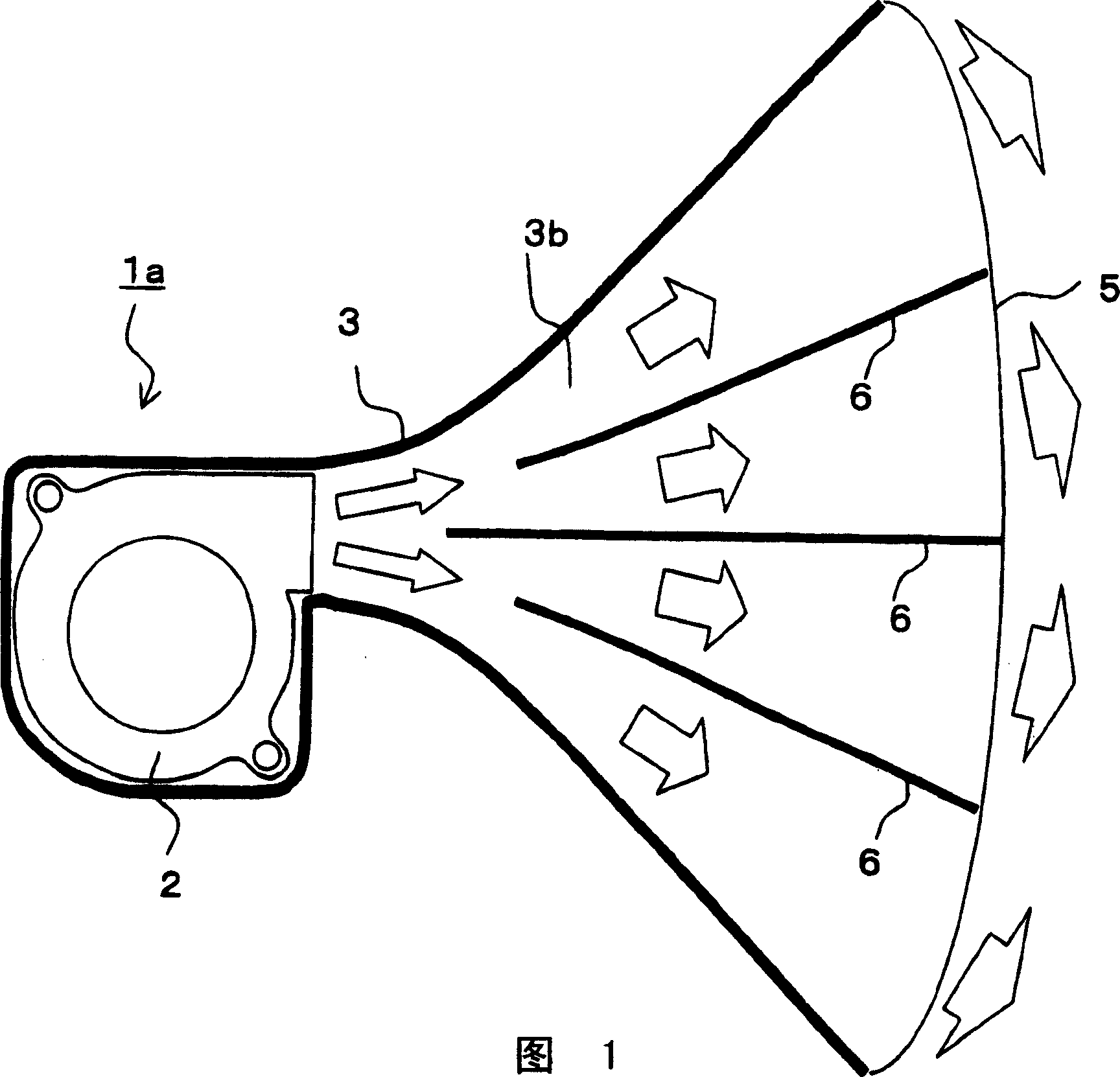
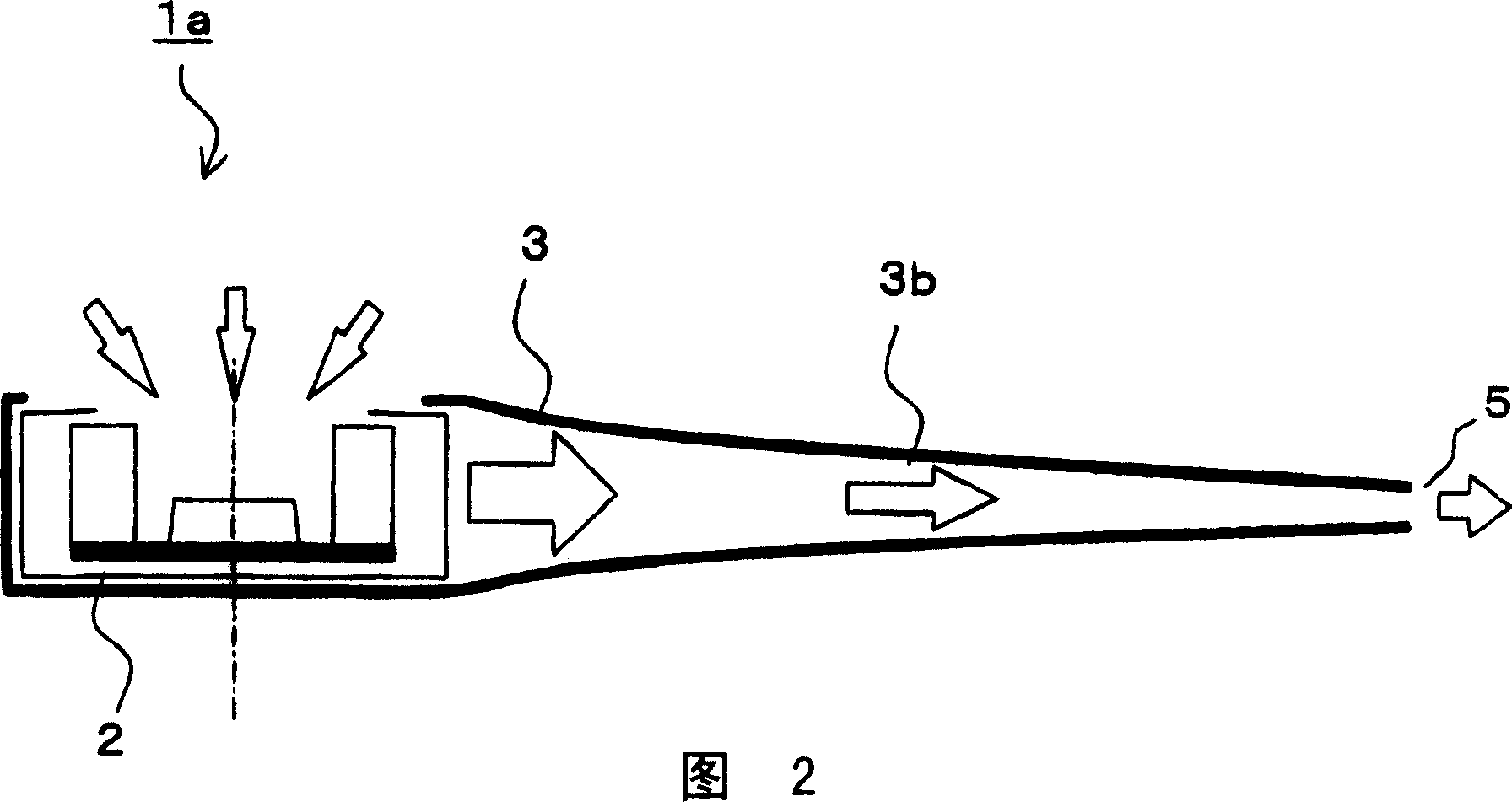
[0101] The first embodiment will be described below. FIG. 1 is a schematic plan cross-sectional view showing the fluid generator of the present embodiment, and FIG. 2 is a schematic side sectional view of the fluid generator of the present embodiment. The fluid generating device 1a of the present embodiment includes a fluid supply device 2 for supplying a fluid such as gas or liquid, a fluid flow channel 3 for supplying the fluid sent from the fluid supply device 2, and a fluid flow channel 3 formed at the end of the fluid flow channel 3 to transfer the fluid. Air outlet 5 sent out in jet form, control part not shown. The fluid is transported by the driving of the fluid supply device 2 , flows through the fluid flow passage 3 , and is discharged from the blower outlet 5 as a jet flow to the outside. The arrows in the figure indicate the flow of the fluid.
[0102] In the fluid flow passage 3, the upstream portion of the blower outlet 5 is constituted by the enlarged pipe por...
no. 2 Embodiment approach
[0116] Next, a second embodiment will be described. Fig. 7 is a schematic plan sectional view showing the fluid generator of the present embodiment. Figure 8 It is a schematic side sectional view showing the fluid generator of this embodiment.
[0117] In this embodiment, instead of the guide plate 6 of the first embodiment, the fluid flow path 3 is divided into a plurality of enlarged pipe portions 3 b from the immediately downstream portion of the fluid supply device 2 . In the present embodiment, the fluid circulation channel 3 is divided into two in the left-right direction and two in the vertical direction, and is divided into four enlarged tube parts 3b in total, so four outlets 5 are provided. In addition, the aspect ratio of the fluid flow channel 3 and each enlarged pipe portion 3b divided by the division area increases as they approach the outlet 5, and the aspect ratio at the location of the outlet 5 is set to about 10. Other structures are the same as those of t...
no. 3 Embodiment approach
[0122] Next, a third embodiment will be described. Figure 10 It is a perspective view which shows the fluid generator of this embodiment.
[0123] In the fluid generator 1d of the present embodiment, the shape of the outlet 5 is height>width, as in another embodiment of the second embodiment. The fluid circulation channel 3 is divided into seven in the left-right direction and two in the up-down direction, and is divided into a total of 14 enlarged tube parts 3b, so that 14 outlets 5 are provided. And it is configured that the aspect ratio of the fluid flow channel 3 and each enlarged pipe portion 3b demarcated by the division increases as they approach the outlet 5, and the aspect ratio at the position of the outlet 5 (in this case, the height of the outlet / the width of the outlet) ) is set at around 8. Other structures are the same as in another embodiment of the second embodiment.
[0124] In this fluid generator 1d, the flow velocity distribution is different from the ...
PUM
 Abstract
Description
Claims
Application Information