LCM process DC resistance real-time monitoring method

A DC resistance, real-time monitoring technology, applied in the direction of material resistance, can solve problems such as improper mold and process design, affecting appearance and component quality, compressive strength, etc., to reduce incomplete mold filling or dry spots, and improve product quality. Instability, the effect of improving product quality

Inactive Publication Date: 2006-10-25
BEIHANG UNIV
View PDF0 Cites 8 Cited by
  • Summary
  • Abstract
  • Description
  • Claims
  • Application Information

AI Technical Summary

Problems solved by technology

Since the quality of components produced by this process largely depends on the flow filling process of resin and its chemical curing reaction, the LCM process itself has obvious disadvantages: such as long resin flow time, improper mold and process design are easy to produce defective products, Typical defects such as dry spots and air bubbles are formed, which seriously affect the appearance and component quality
[0008] Optical fiber sensing technology has a series of unique advantages that are difficult to compare with other sensing technologies, such as a variety of monitoring and measurement of various physical quantities, light weight, small size, easy to embed in structures, high sensitivity, and is not immune to electromagnetic waves. , radio frequency interference, etc., but it also has some inevitable defects. For composite materials, the embedded optical fiber sensor affects the integrity of the main component of the composite material due to interference with the local strain field of the fiber-matrix interface, causing stress concentration. will degrade the performance of the structure
Most experiments show that optical fibers with a diameter of 125 μm or less have no obvious effect on the damage behavior, tensile strength, Poisson's ratio, etc. of the composite material, but have a significant effect on the compressive strength of the composite material, and the strength drops by about 24 to 60%. , also has a significant effect on the fatigue life
Therefore, real-time monitoring of LCMs using fiber optic sensing technology is limited

Method used


Image

  • LCM process DC resistance real-time monitoring method
  • LCM process DC resistance real-time monitoring method
  • LCM process DC resistance real-time monitoring method

Examples


Embodiment Construction

[0018] Such as figure 1 , 2 Shown, concrete steps of the present invention are as follows:

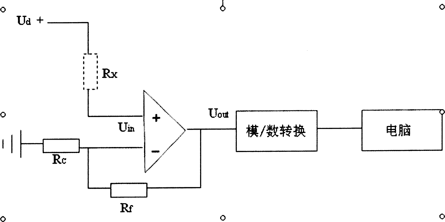
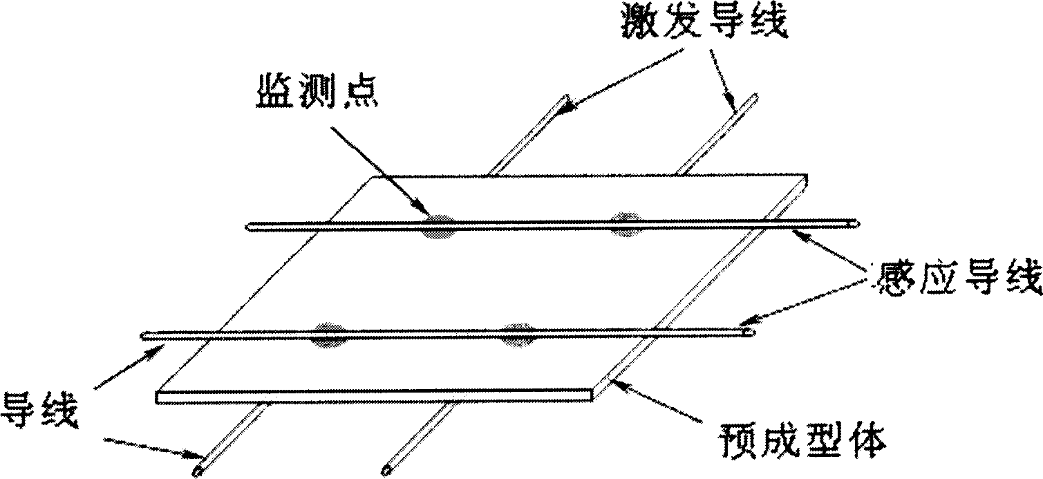
[0019] (1) According to the size of the component, the upper and lower surfaces are criss-crossed, the upper surface is discharged with excitation wires, and the lower surface is discharged with induction wires. The intersection of each excitation wire and induction wire is the monitoring point, and its resistance value R x For the resistance at the monitoring point of the preform, the monitoring points should be evenly distributed on the entire surface of the component for overall monitoring of the filling process; the points that may have process defects are also found through process simulation and used as monitoring points.

[0020] (2) A reference resistor R is connected in series for the preform monitoring point c ,R c The value selection method is as follows: firstly, through trial and error, the preform resistance R x The value is roughly measured, and then selected with R ...


PUM


Abstract

The invention relates to LCM technology DC resistance real time monitoring method. It includes the following steps: pre-molding cross laying laser wire and inducing wire determine monitoring point; applying DC voltage to the two sides of the point and connecting ratio resistance to form divider circuit, measuring the voltage of the resistance that could be gathered and displayed by PC, the tested pre-molding body resistance would be gained after calculating; taking resin filling mould and recycling scanning all the monitoring points to judge the arrival of the resin flow peel; after filling mould, the pre-molding resistance of every monitoring point is increased, monitoring the alteration of the body resistance, the resin solidifying situation would be monitored. The invention could decrease defective percent, improve product quality, and effectively solve the product quality unstable problem in the producing of resin based compound material.

Description

technical field [0001] The invention relates to a real-time monitoring method of composite material liquid molding process LCM. Background technique [0002] Composite liquid molding process LCM (Liquid Composites Molding) refers to injecting a special liquid low-viscosity resin under a certain pressure into a closed cavity pre-laid with fiber reinforced materials or heating and melting the resin film in the cavity, and the resin flows and infiltrates. It is an advanced composite material process method that strengthens materials and solidifies them. It is widely used in aerospace, automobile, shipbuilding, construction and other industries. The LCM process is a one-step molding process, which has the advantages of flexible operation, strong designability, low equipment and process costs, and basically no pollution to the environment. Since the quality of components produced by this process largely depends on the flow filling process of resin and its chemical curing reactio...

Claims


Application Information

Patent Timeline
Patent Type & Authority Applications(China)
IPC IPC(8): G01N27/10B29C70/54
Inventor 段跃新孙玉敏张佐光
Owner BEIHANG UNIV
Why Eureka
Try Eureka