
Cable component test system and device

A cable component and test system technology, applied in the field of communication, can solve the problems of high test cost and low test efficiency of cable components, and achieve the effect of reducing test cost, improving test speed and test efficiency

Inactive Publication Date: 2006-11-08
HUAWEI TECH CO LTD
View PDF1 Cites 9 Cited by
  • Summary
  • Abstract
  • Description
  • Claims
  • Application Information

AI Technical Summary

Problems solved by technology

[0005] The purpose of the present invention is to solve the problems of low test efficiency and relatively high test cost of cable assemblies existing in the prior art

Method used


Image

  • Cable component test system and device

Examples


Embodiment Construction

[0034] In order to make the object, technical solution and advantages of the present invention clearer, the present invention will be further described in detail below in conjunction with the accompanying drawings and embodiments. It should be understood that the specific embodiments described here are only used to explain the present invention, not to limit the present invention.

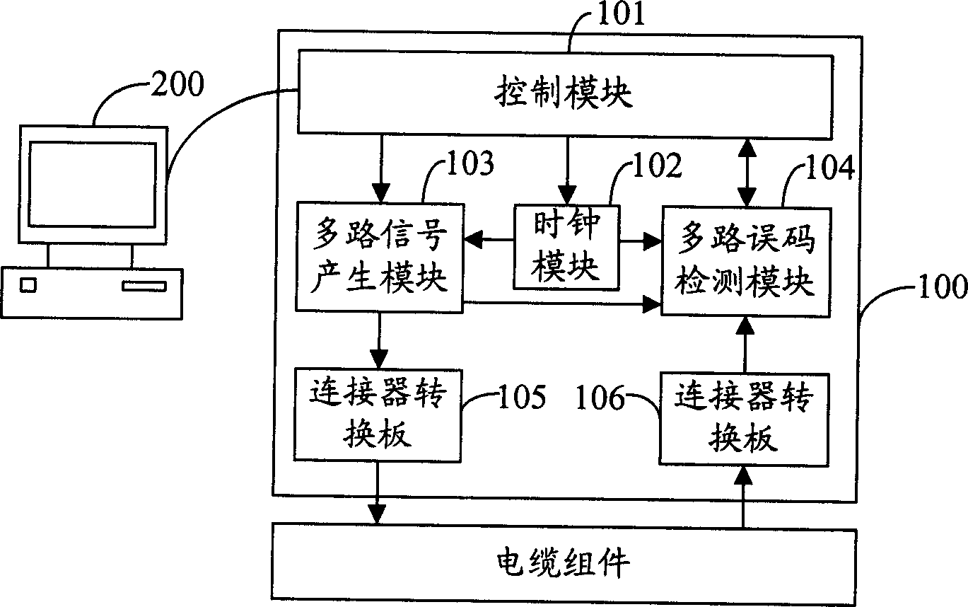
[0035] figure 1 Shown is the composition of the cable assembly testing device provided by the present invention, which mainly includes a host 100 and a control computer 200 connected to and communicating with the host 100 . The control computer 200 communicates with the host computer 100 through the software interface, edits and distributes relevant test parameters of the cable assembly, receives test results reported by the host computer 100, and outputs reports, etc. A cable assembly consists of a cable and connectors on one or both ends of the cable.

[0036] The host 100 includes a control mo...


PUM


Abstract

This invention provides a cable component test system and a device, in which, the system includes: a host for testing the cable components based on their test parameters to output test results and a control computer connected with the host used in providing test parameters of the components to the host and receiving test results reported by the host, which also includes a control module, a clock module, a multiple signal generating module, a multiple error code testing module and a switch board of a connector.

Description

technical field [0001] The invention belongs to the communication field, in particular to a system and a device for testing cable components. Background technique [0002] At present, there are two main types of testing for cable assemblies in the industry: index testing and functional testing. Index test mainly tests the frequency domain of cable components, such as insertion loss (Insert loss), return loss (Returnloss), impedance (Impedance), crosstalk (Crosstalk), line pair difference (Skew) and delay (Delay), etc., using The main instrument is the network analyzer (Network Analyzer). When using a network analyzer for index testing, only one pair of differential lines can be tested at a time, or the crosstalk between a pair of differential lines and another pair of differential lines, etc., and it is not possible to test multiple pairs of differential lines at the same time. due to its own characteristics. At the same time, the switching efficiency of the test channel ...

Claims


Application Information

Patent Timeline
IPC IPC(8): G01R31/08G01R31/00
Inventor 莫道春方炜
Owner HUAWEI TECH CO LTD
Learn More