
Cleanup method for optics in immersion lithography

An optical system and immersion technology, which can be used in cleaning methods, cleaning methods and utensils using liquids, microlithography exposure equipment, etc., which can solve the problems of time-consuming and cumbersome

Inactive Publication Date: 2006-11-22
NIKON CORP
View PDF1 Cites 24 Cited by
  • Summary
  • Abstract
  • Description
  • Claims
  • Application Information

AI Technical Summary

Problems solved by technology

[0008] However, removing an optic and resetting it after cleaning or replacing the optic with a new one is a tedious and time-consuming operation

Method used


Image

  • Cleanup method for optics in immersion lithography
  • Cleanup method for optics in immersion lithography
  • Cleanup method for optics in immersion lithography

Examples


Embodiment Construction

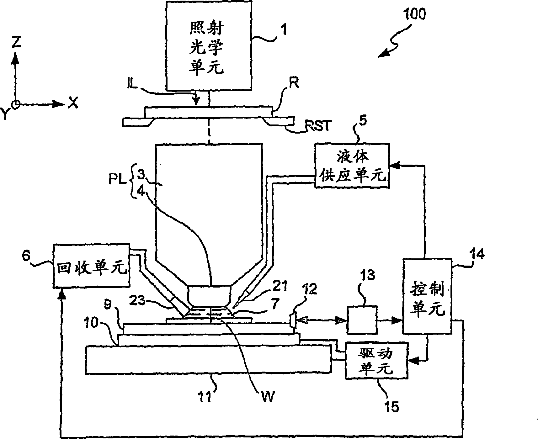
[0029] figure 1 An immersion lithography apparatus 100 is shown on which the method and system of the present invention may be applied.

[0030] Such as figure 1 As shown, the immersion lithography apparatus 100 includes an illumination optics unit 1, which includes a light source such as an excimer laser unit, an optical integrator (or homogenizer) and a lens, and the illumination optics unit is used to emit wavelength The ultraviolet light IL of 248nm is incident on the pattern on the reticle R. The pattern on the reticle R is projected onto the wafer W coated with photoresist at a specified magnification (eg 1 / 4 or 1 / 5) by a telecentric light projection unit PL. Pulsed light IL can be selected from ArF excimer laser with a wavelength of 193nm, and F excimer laser with a wavelength of 157nm 2 Excimer laser light, or mercury lamp i-line with a wavelength of 365nm. Subsequently, when describing the structure and function of the lithography apparatus 100, use figure 1 The ...


PUM


Abstract

An immersion lithography apparatus has a reticle stage arranged to retain a reticle, a working stage arranged to retain a workpiece, and an optical system including an illumination source and an optical element opposite the workpiece for having an image pattern of the reticle projected by radiation from the illumination source. A gap is defined between the optical element and the workpiece, and a fluid-supplying device serves to supply an immersion liquid into this gap such that the supplied immersion liquid contacts both the optical element and the workpiece during an immersion lithography process. A cleaning device is incorporated for removing absorbed liquid from the optical element during a cleanup process. The cleaning device may make use of a cleaning liquid having affinity to the absorbed liquid, heat, a vacuum condition, ultrasonic vibrations or cavitating bubbles for the removal of the absorbed liquid. The cleaning liquid may be supplied through the same fluid-applying device provided with a switching device such as a valve.

Description

[0001] Related patent application reference [0002] This application claims priority to U.S. Provisional Patent Application No. 60 / 462,556, filed April 11, 2003, and U.S. Provisional Patent Application No. 60 / 482,913, filed June 2003 The application was filed on the 27th, and its content is cited herein as a reference. technical field [0003] The present invention relates to an immersion lithography system, and more particularly, in addition to the system, to a method for cleaning an optical element that contacts and absorbs water during an immersion lithography process. Background technique [0004] The immersion lithography system is used to provide liquid in the space between the workpiece, such as a wafer, and the last optical element of the optical system, and is used to project the image of the reticle onto the workpiece. This immersion lithography system is such as Disclosed in WO99 / 49504, the contents of which are cited herein to illustrate the general background ...

Claims


Application Information

Patent Timeline
IPC IPC(8): G03B27/42B08B3/04B08B3/12G03F7/20
CPCB08B3/04B08B3/12G03F7/2041G03F7/70341G03F7/70891G03F7/70916G03F7/70925H01L21/0274
Inventor 安德鲁·J·黑兹尔顿川井秀实道格拉斯·C·沃特森托马斯·W·诺万克
Owner NIKON CORP
Learn More