Heat distortion compensation method of digial controlled machine tool main driving system

A main drive system, CNC machine tool technology, applied in automatic control devices, metal processing mechanical parts, metal processing and other directions, can solve the problems of poor accuracy stability, many accessory parts, poor accuracy and accuracy stability, etc.

Inactive Publication Date: 2006-11-29
四川长征机床集团有限公司
View PDF0 Cites 42 Cited by
  • Summary
  • Abstract
  • Description
  • Claims
  • Application Information

AI Technical Summary

Problems solved by technology

[0010] The above method has the following disadvantages: there are many auxiliary parts used, the changes to the machine tool are relatively large, the cost is high, and the way to reduce the temperature rise is fuzzy control, and the accuracy and stability of the accuracy after compensation are still poor;
[0012] fr...

Method used


Image

  • Heat distortion compensation method of digial controlled machine tool main driving system
  • Heat distortion compensation method of digial controlled machine tool main driving system
  • Heat distortion compensation method of digial controlled machine tool main driving system

Examples


Embodiment 1

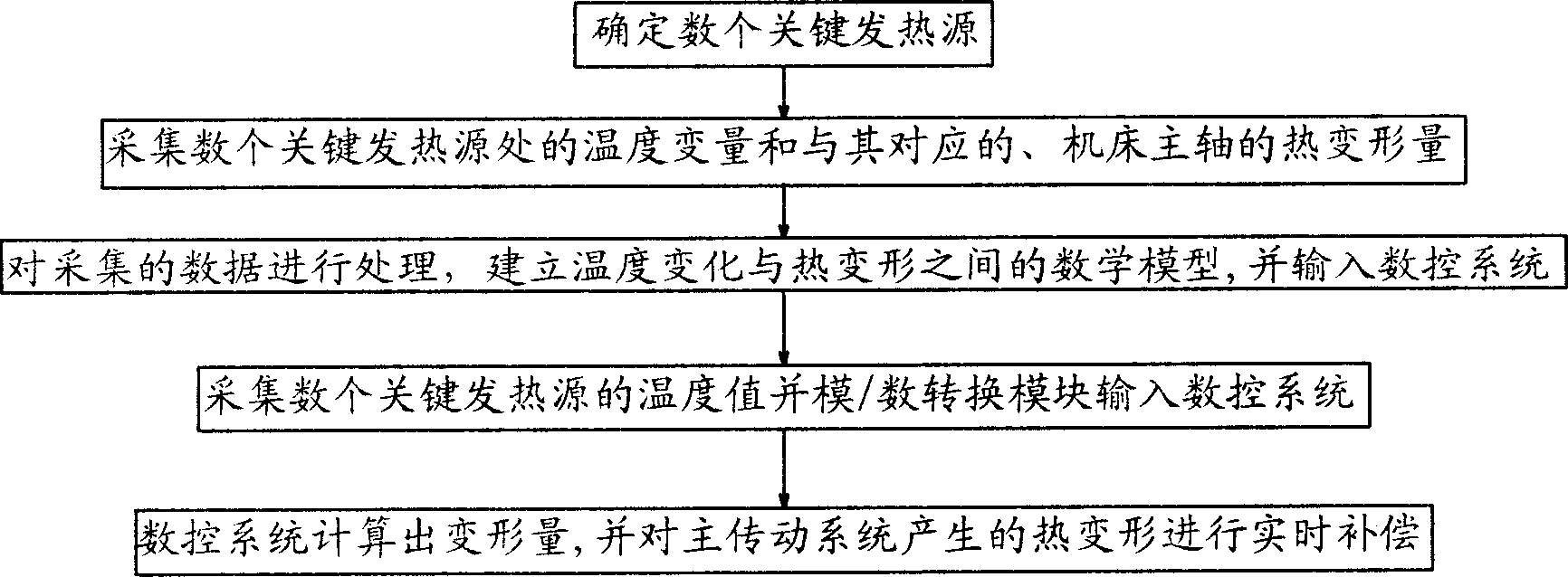
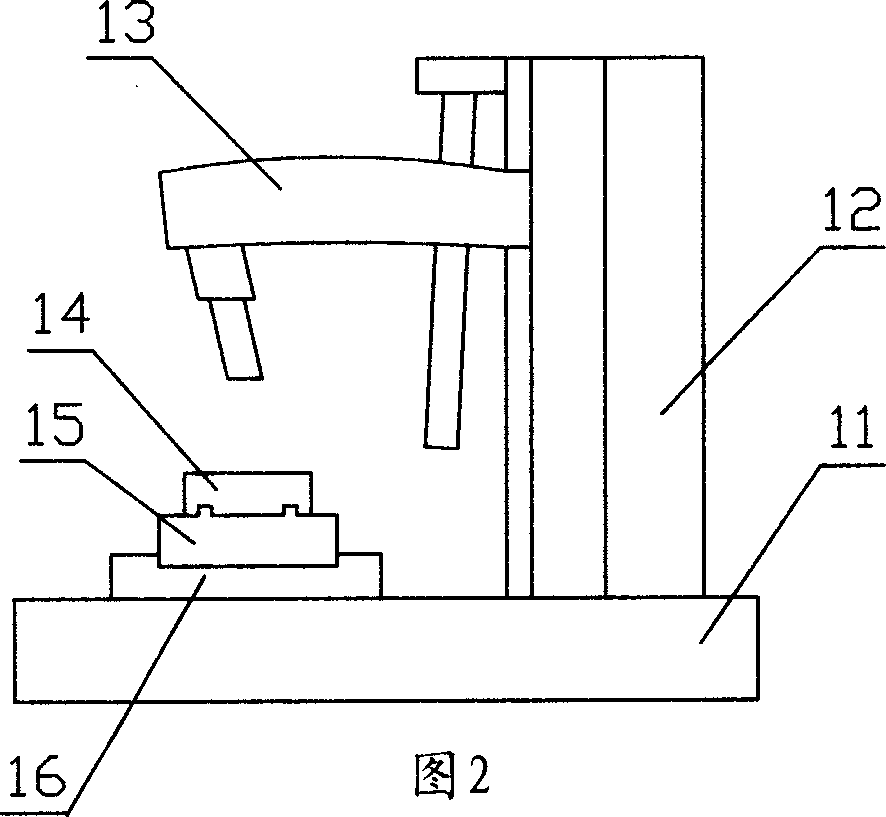
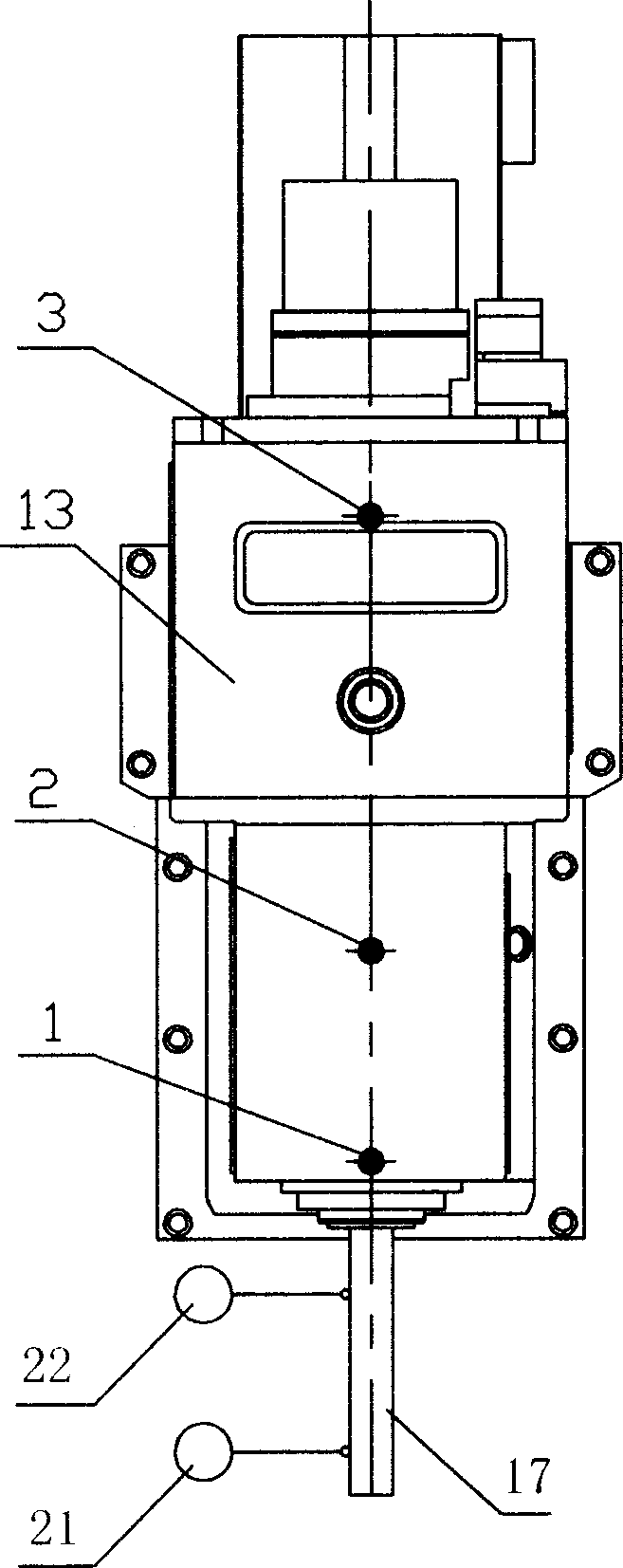
[0131] 2. By setting two temperature sensors 3, 1 (PT100 type platinum thermistor) respectively on the main shaft housing 13 corresponding to the upper and lower bearing pairs of the main shaft, as Figure 5 , as shown in Figure 6, a standard inspection mandrel 17 is installed on the main shaft, and two dial gauges 23 and 24 with a distance of 250 mm are respectively installed in the YZ plane, and the contacts of the dial gauge are aligned with the center of the standard inspection mandrel 17 Line and align to zero, install a dial indicator 25 on the end face of the main shaft, respectively collect the temperature variables at the two key heat sources and the corresponding thermal deformation of the machine tool main shaft in the Y direction and Z direction at this moment;

[0132] After starting the machine tool, the machine tool spindle starts to run step by step from low speed to high speed. At a fixed time interval, check and record the two temperature variables and the the...

Embodiment 2

[0142] 2. By setting the three temperature sensors 1, 3, 5 respectively on the lower bearing pair corresponding to the main shaft, the upper bearing pair and the main shaft case of the gearbox, such as Figure 5 , as shown in Figure 6, a standard inspection mandrel 17 is installed on the main shaft, and two dial gauges 23 and 24 with a distance of 250 mm are respectively installed in the YZ plane, and the contacts of the dial gauge are aligned with the center of the standard inspection mandrel 17 line and zero, a dial indicator 25 is installed on the end face of the main shaft, and the temperature variables at the three key heat sources and the corresponding thermal deformations of the main shaft of the machine tool in the Y direction and Z direction are collected respectively; Embodiment one is identical;

[0143] 3. Use the method of multiple linear regression to process the temperature variable and thermal deformation collected in step (2), and establish the mathematical re...


PUM


Abstract

A thermal deformation compensating method for the main drive system of numeral controlled machine-tool includes such steps as determining several important heat generating sources of numeral controlled machine-tool, acquiring their temp variables and relative thermal deformations of mainshaft, processing them to obtain a mathematical model between temp variation and thermal deformation of mainshaft, inputting it to the numeral control system, acquiring the temp values of several important heat sources, inputting them to the numeral control system, calculating the thermal deformation of mainshaft, and real-time compensation by driving the transmission part.

Description

technical field [0001] The invention relates to a method for compensating the thermal deformation of the main transmission system of a numerical control machine tool. Background technique [0002] Although the CNC machine tools commonly used in the mechanical processing industry have greatly improved the accuracy compared with traditional machine tools, there is still a certain deviation from the design value. The factors that affect the machining accuracy of CNC machine tools are X, Y, and Z three-axis feed system The positioning error and the thermal deformation error caused by various heat sources, the former is mainly caused by the manufacturing error and assembly error of the screw, bearing, installation parts, etc. However, the positioning error of the X, Y, Z three-axis feed system can be adopted Full closed-loop control, the real displacement of the moving parts is fed back through the grating ruler, and the numerical control system compensates to eliminate the posit...

Claims


Application Information

Patent Timeline
IPC IPC(8): B23Q15/007B23Q15/18
Inventor 徐中行林健王东马术文刘柯
Owner 四川长征机床集团有限公司
Why Eureka
Try Eureka