Microdissection device based on piezoelectric ultrasonic vibration

A technology of microdissection and piezoelectric ultrasound, which is applied in the fields of sampling device, medical science, inoculation and ovulation diagnosis, etc. It can solve the problems of high work intensity, easy fatigue and human error of the operator

Inactive Publication Date: 2006-12-13
HARBIN INST OF TECH
View PDF0 Cites 12 Cited by
  • Summary
  • Abstract
  • Description
  • Claims
  • Application Information

AI Technical Summary

Problems solved by technology

[0003] The purpose of the present invention is to provide a micro-cutting device based on piezoelectric ultrasonic vibration to overcome the defects o

Method used


Image

  • Microdissection device based on piezoelectric ultrasonic vibration
  • Microdissection device based on piezoelectric ultrasonic vibration

Examples


specific Embodiment approach 1

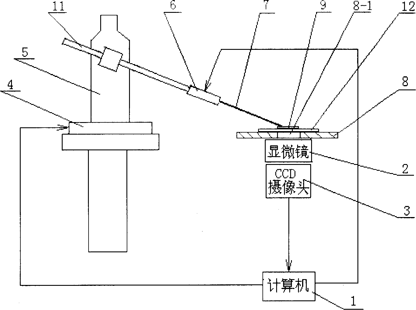
[0005] Specific implementation mode one: the following combination figure 1 with figure 2 This embodiment will be specifically described. This embodiment is composed of a computer 1, a microscope 2, a CCD camera 3, a three-degree-of-freedom mechanical micro-motion table 4, a clamp body 5, an ultrasonic vibration generator 6, a cutting needle 7, a biological slice platform 8, and a tool bar 11. The microscope 2 is arranged under the opening 8-1 of the biological slice stage 8, the CCD camera 3 is connected to the microscope 2 to collect the object image enlarged by the microscope 2, the signal output end of the CCD camera 3 is connected to the signal input end of the computer 1, The mechanical micro-motion table 4 with three degrees of freedom in space is arranged on the side of the biological slice platform 8, and one signal output terminal of the computer 1 is connected to the controlled end of the mechanical micro-motion table 4 with three degrees of freedom in space to re...

specific Embodiment approach 2

[0006] Specific implementation mode two: the following combination figure 1 This embodiment will be specifically described. The difference between the present embodiment and the first embodiment is that the ultrasonic vibration generator 6 uses an ultrasonic transducer or a stacked ceramic driver. Other components and connections are the same as those in Embodiment 1.


PUM


Abstract

The invention relates the microscopic cutting device. The invention overcomes the defects of strong working strength, fatigability and big personal error. The device comprises computer 1, microscope 2, CCD cam 3, free mechanical micro motion desk 4, clamp 5, ultrasonic vibration emitter 6, cutting needle 7, biological section stage 8 and cutter bar. 2 is installed under 8, 3 is connected with 2 to collect the object magnified by 2, the signal output terminal of 3 is connected with signal input terminal of 1, 4 is installed at the side of 8, the signal output terminal of 1 is connected with controlling terminal of 4, 5 is fixed on the 4, 11 is fixed on the 5, one end of 11 is connected with one end of 6, the other end of 6 is connected with the butt of 7, the tip of 7 extends to the upper surface of 8, and the other signal output terminal of 1 is connected with the input terminal of 6.

Description

technical field [0001] The invention belongs to a cutting and separating device for biological tissue slices in biomedicine. Background technique [0002] With the improvement of bioengineering and medical research, biomedicine has developed to the stage of exploring the pathogenesis of diseases and revealing the essence of life phenomena at the molecular level. Microscopic analysis of pathological slides is one of the most effective and accurate methods. However, to analyze the pathological mechanism or analyze the gene arrangement, it is necessary to extract the specified cell tissue area from the slice. Therefore, in molecular pathology research, how to select and collect the required research materials is also a relatively common problem. At present, the cutting and separation of biological tissue slices are generally done manually, and the operator has high work intensity, fatigue, and human errors are inevitable. Therefore, it is of great significance to study a mic...

Claims


Application Information

Patent Timeline
IPC IPC(8): A61B19/00A61B10/00G01N1/06
Inventor 陈立国荣伟彬刘亚欣王会香
Owner HARBIN INST OF TECH
Why Eureka
Try Eureka