
Thermally conductive glue and method of manufacturing same

A technology of thermally conductive adhesives and thermally conductive fillers, applied in the direction of adhesives, epoxy resin glue, adhesive types, etc., can solve the problems of reducing interface impedance, reducing the proportion of thermally conductive fillers, increasing interface thermal resistance, etc., to achieve reduction Small thermal resistance, avoiding excessive thermal resistance, and improving thermal conductivity

Inactive Publication Date: 2006-12-20
HONG FU JIN PRECISION IND (SHENZHEN) CO LTD +1
View PDF0 Cites 27 Cited by
  • Summary
  • Abstract
  • Description
  • Claims
  • Application Information

AI Technical Summary

Problems solved by technology

[0004]The first type is ceramic heat-conducting adhesive materials, which use ceramic gaskets as heat-conducting gaskets, and are mainly flakes such as mica and graphite. Apply thermal paste to reduce interface impedance, the disadvantage is that it is easy to break and unfavorable for cutting
[0005]The second type is thermal pads, which are thermal pads made by coating thermally conductive polymer materials on glass fiber cloth. Tensile strength and softness, etc., easy to cut and not easy to break, the disadvantage is that the thickness of the glass fiber cloth is greater than 0.05mm, and the total thickness of the coated polymer material cannot be less than 0.1mm, so the thermal resistance value is relatively high, and it is currently used in low heating element
[0006]The third category is thermally conductive adhesive, which is made of liquid or semi-solid thermally conductive adhesive by adding ceramic powder, graphite or metal powder to liquid polymer. The advantage is low thermal resistance value and good heat transfer effect. Its disadvantage is that it is easy to contaminate electronic components and circuit boards when used, and it may dry out and volatilize small molecular substances at high temperatures.
However, the proportion of internal thermal conductive filler is relatively small, resulting in low thermal conductivity of the thermal conductive adhesive
However, when the proportion of the thermally conductive filler increases, the viscosity of the thermally conductive adhesive rises sharply, which eventually causes the thermally conductive adhesive to lose its fluidity. In this way, the thermally conductive filler and the matrix cannot be mixed uniformly during the manufacturing process of the thermally conductive adhesive, resulting in thermally conductive filling. There is a gap between the objects, which will cause the thermal conductivity of the thermal adhesive to decrease and increase the interface thermal resistance.

Method used


Image

  • Thermally conductive glue and method of manufacturing same
  • Thermally conductive glue and method of manufacturing same

Examples


Embodiment Construction

[0033] The technical solution will be described in further detail below in conjunction with the accompanying drawings.

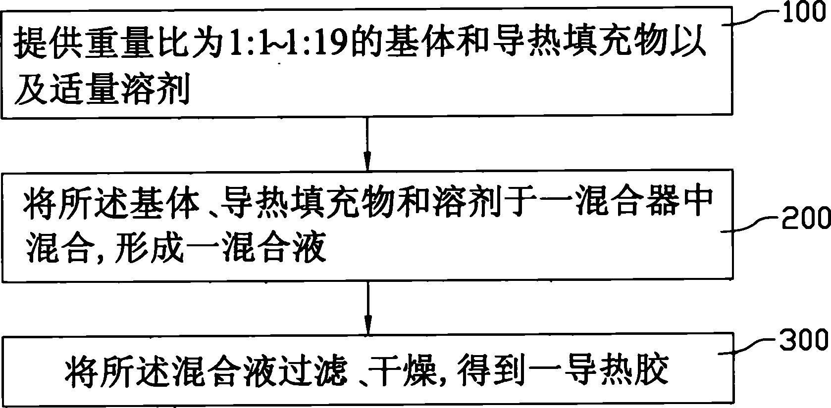
[0034] see figure 1 , the preparation method of the thermally conductive adhesive provided by the technical solution, which includes the following steps: providing a predetermined ratio of a matrix, a thermally conductive filler, and an appropriate amount of solvent, so that the ratio of the matrix to the thermally conductive filler reaches 1:1 to 1:19; The matrix, the heat conduction filler and the solvent are mixed in a mixer to form a mixed liquid; the mixed liquid is filtered and dried to obtain a heat conduction adhesive. The method for preparing the thermally conductive adhesive provided by the technical solution will be described in detail below in conjunction with the examples.

[0035] Step 100: providing a matrix, a thermally conductive filler, and an appropriate amount of solvent in a weight ratio of 1:1˜1:19. The matrix can be selected from a p...


PUM


Abstract

This invention provides a heat conducting gel and method for making same. The heat conducting gel comprises a base body and heat conducting filler homogenously dispersed inside the base body, wherein the said heat conducting filler takes up 50-95wt% of the whole heat conducting gel. The procedures of producing the heat conducting gel comprise: provide the base body and the heat conducting filler at the weight ratio of 1:1-1:19, and right amount of solvent; mix the above base body, heat conducting filler and solvent in the agitator to form the mixing solution; filtrate and dry the above mixing solution to obtain the heat conducting gel. The heat conducting gel of this invention is characterized that the heat conducting filler takes up a high weight percentage, and is homogenously dispersed inside the base body, which can form large physical contact between the heat conducting interface, avoid producing too much heat resistance and greatly reduce the heat resistance between the heat conducting interface.

Description

【Technical field】 [0001] The invention relates to a thermal interface material, in particular to a thermally conductive adhesive with a thermally conductive filler and a preparation method thereof. 【Background technique】 [0002] As integrated circuits become denser and miniaturized, electronic components become smaller and operate at higher speeds, placing ever higher demands on heat dissipation. Therefore, in order to dissipate the heat from the heat source as soon as possible, it has become a common practice in the industry to install a heat sink on the surface of the electronic component. It utilizes the high thermal conductivity of the material of the heat sink to quickly dissipate the heat to the outside. However, the surface of the heat sink and the heat source There is often a certain gap at the contact interface, so that the surface of the heat sink and the heat source are not in close contact, which becomes a major defect in the heat dissipation of the heat sink. ...

Claims


Application Information

Patent Timeline
IPC IPC(8): C09J9/00C09J131/04C09J123/06C09J183/04C09J127/06C09J167/00C09J163/00
Inventor 萧博元何纪壮
Owner HONG FU JIN PRECISION IND (SHENZHEN) CO LTD
Features
  • Generate Ideas
  • Intellectual Property
  • Life Sciences
  • Materials
  • Tech Scout
  • Unparalleled Data Quality
  • Higher Quality Content
  • 60% Fewer Hallucinations
Learn More