Punch-shearing machine

A stamping shearing and frame technology, which is applied in the direction of shearing devices, nibbling cutting devices, shearing equipment, etc., can solve the problems of laborious operation, incompetent processing, and lengthy processing process without contamination of metal shavings

Inactive Publication Date: 2006-12-27
常熟市卫江机械有限公司
View PDF2 Cites 4 Cited by
  • Summary
  • Abstract
  • Description
  • Claims
  • Application Information

AI Technical Summary

Problems solved by technology

This technical scheme has the advantages of simple structure, but there are following deficiencies. The one is that it can only punch and shear various iron sheets with a thickness of about 1 mm, but there is nothing that can be done for thicker iron sheets, especially for angle irons, round iron sheets, etc. Steel, flat steel, and square steel cannot be handled by this kind of shearing punching machine; the second is that the operation is more laborious and inefficient. Drive the tooth plate meshed with the pressure bar gear, the tooth plate drives the pressure plate, and then the pressure plate drives the slider installed with the profile shearing blade to move down along the sliding plate, so that the profile shearing edge cooperates with the fixed shearing edge to cut the profile, it can be seen , there are many transmission steps in which the force is gradually transmitted from the pressure rod to the profile cutting edge, resulting in a large loss of force, so it is very laborious and extremely inefficient; the third is to observe its working principle from the overall structure. stamping factor
[0003] Chinese patent authorization announcement number CN2740331Y discloses a multi-functional stamping and shearing machine. Compared with the previous patent, it has the advantages of labor saving and relatively improved efficiency, but there are still the following disadvantages. One is that an oil cylinder is used, so it must be equipped with an oil tank. and other supporting parts, resulting in an increase in equipment costs; second, the cylinder stamping and shearing plate is characterized by static pressure or extrusion, and the biggest disadvantage of static pressure (extrusion) is that it can only be suitable for the thin sheet iron sheet; the third is due to the working process There is no inertia effect in the form of increased force, so as mentioned above, it is not competent for the processing of angle iron, round steel, flat steel and square steel.
[0004] Since the above two kinds of punching and shearing devices are not capable of effectively processing some structural parts such as angle irons and wires in construction sites, workshops, etc. The cutting process still uses the traditional cutting machine, but the use of the traditional cutting machine often results in loud noise in the workplace, serious pollution of metal shavings, and lengthy processing process

Method used


Image

  • Punch-shearing machine
  • Punch-shearing machine

Examples


Embodiment Construction

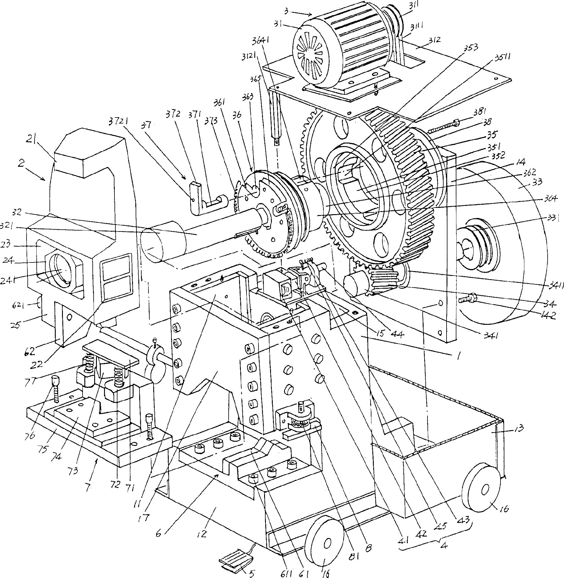
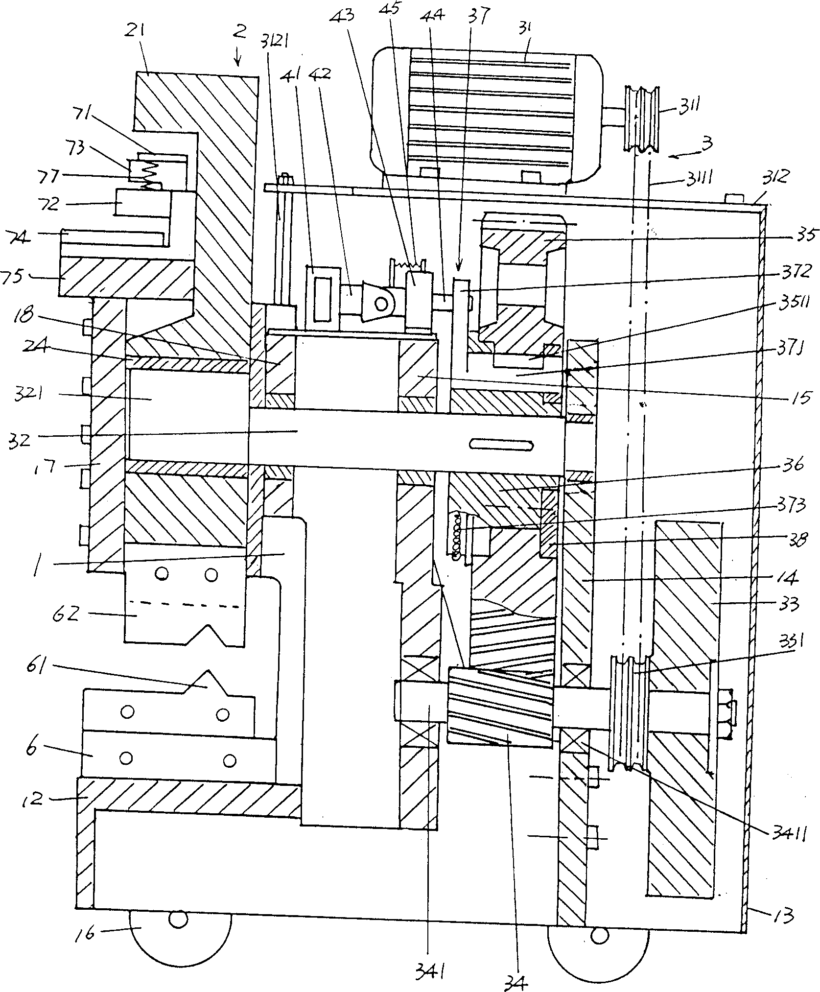
[0018] please see figure 1 and combine figure 2 , the upper front side of the frame 1 is processed with a slider cavity 11, the front side mentioned here refers to the side facing the operator in use, the cavity of the slider cavity 11 is the third wall plate 17 shields, a certain distance is reserved between the third wall plate 17 and the blanking mold base 12, and the working area is formed by this distance. The punch slider 2 is accommodated in the cavity area of ​​the slider cavity 11. In order to obtain a good lubrication effect between the two sides of the punch slider 2 and the two inner walls of the slider cavity 11, it can be recessed in the punch The oil channels 22 on the lower part of both sides of the slide block 2 replenish lubricating oil, so that the up and down movement of the punch slide block 2 is flexible. The sliding sleeve 24 arranged in the sliding sleeve hole 23 at the lower part of the punch slider 2 is connected with the transmission mechanism 3 i...


PUM


Abstract

A stamping and shearing machine, used for punching angle iron, round steel, flat steel, square steel, and also for punching square hole, round hole, slotted hole, chamfer, bending etc., belongs to field of punching mechanism technology, which includes stand frame, punch slider, drive mechanism, electric-magnet control mechanism with treading type switch. A slider cavity is provided on top of stand frame foreside, and a material cutting die bed is formed corresponding to the underpart of the cavity. The punch slider is slide-adapted in the slider cavity. The drive mechanism includes electric motor, flywheel, pinion, big gear, clutch, clutch-link, camshaft. Advantages are: the drive mechanism can provides perfect punching shearing force to sliding punch, not only the defect of laborious manual operation and sheet iron shearing punching only in present technology is compensated, but also has eliminated the bewilderment of the machining-incapable of angle iron, round steel, flat steel and square steel by hydro-cylinder static pressure. The integral volume is small and presentesmobility, which provides maneuver and flexible convenience for field job location, for example building site and workshop.

Description

technical field [0001] The invention relates to a stamping and shearing machine, which is used for punching and shearing angle iron, round steel, flat steel, square steel and punching square holes, round holes, long holes, corner cutting, bending, etc., and belongs to the technical field of punching and shearing machinery. Background technique [0002] Chinese Patent Authorization Announcement No. CN2142381Y discloses a manual multifunctional shearing punching machine, which is composed of a fuselage, a movable profile cutting blade, a sliding plate, an adjusting screw, a pressing plate, and a pressing bar. The lower end of the plate has a plate shearing edge and a punching die fixing installation hole at the same time, and correspondingly there is a plane workbench at the bottom of the fuselage. This technical scheme has the advantages of simple structure, but there are following deficiencies. The one is that it can only punch and shear various iron sheets with a thickness ...

Claims


Application Information

Patent Timeline
IPC IPC(8): B21D28/00B21D28/20B21D28/14B23D27/00B23D35/00B23D36/00
Inventor 陈卫刚陈耀良
Owner 常熟市卫江机械有限公司
Why Eureka
Try Eureka