Zooming apparatus of long-distance large-range semiconductor laser lighting device

A semiconductor, a wide range of technology, used in semiconductor lasers, lasers, laser parts and other directions, can solve the problems of high cost, unfavorable installation, energy waste, etc., to achieve the effect of low cost, simple implementation and small size

Inactive Publication Date: 2006-12-27
山东神戎电子股份有限公司
View PDF2 Cites 4 Cited by
  • Summary
  • Abstract
  • Description
  • Claims
  • Application Information

AI Technical Summary

Problems solved by technology

However, this method brings more unfavorable factors. The increase in power consumption requires a high heat dissipation system and power supply, otherwise it will affect the life of the laser, and its volume and weight will also increase, which is not conducive to installation.
In addition, high-power lasers generally require fiber-coupled output, which requires expensive optical components such as microlens arrays and self-focusing lenses, resulting in very high costs.
In addition, during long-distance imaging, the laser still maintains a large-angle irradiation, which seriously wastes energy.

Method used


Image

  • Zooming apparatus of long-distance large-range semiconductor laser lighting device
  • Zooming apparatus of long-distance large-range semiconductor laser lighting device
  • Zooming apparatus of long-distance large-range semiconductor laser lighting device

Examples


Embodiment 1

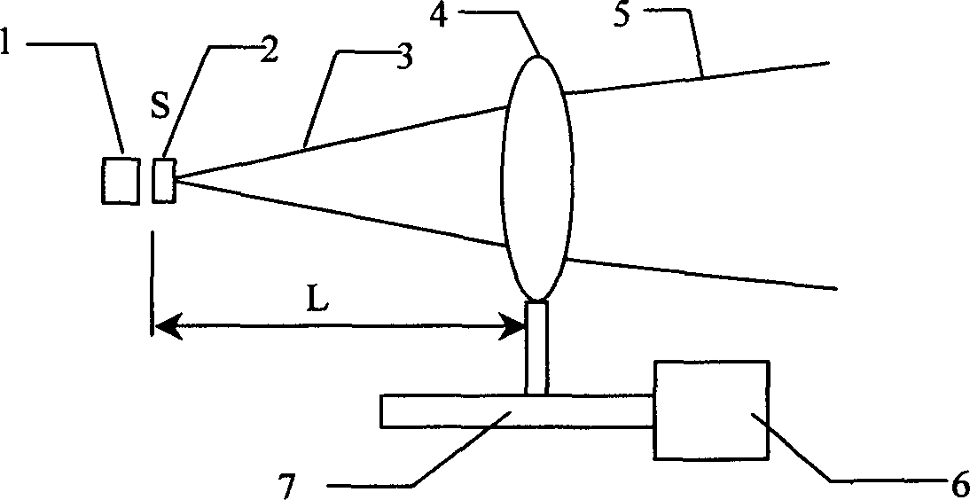
[0028] Such as figure 1 As shown, the beam emitted by the semiconductor laser 1 is usually about 10° (horizontal) × 40° (vertical), and the horizontal and vertical divergence angles are adjusted to be basically the same through the shaping optical device 2 . After shaping, the light beam 3 is angle-compressed by the thin lens group 4 with positive refractive power, and emerges as the outgoing light beam 5. The angle of the outgoing light is related to the distance L, and L is the distance between the light source s and the thin lens group 4 . The motor 6 converts the rotational motion into a linear motion through the mechanical transmission mechanism 7, drives the lens 4 to move back and forth, and adjusts the distance L, thereby controlling the outgoing angle of the outgoing light beam 5. During the forward and backward movement of the thin lens group 4, it is always ensured that the light source S is located on the optical axis of the thin lens group 4, and the entire optic...

Embodiment 2

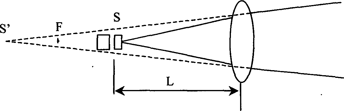
[0030] The angle of the outgoing beam is determined by the divergence angle θ of the light source S after shaping, the focal length f of the lens, and the distance L between the lens and the light source. Such as figure 2 As shown, in particular, the light source S is located within the front focal point F of the lens, and becomes a virtual image light source S' after passing through the lens, and the angle of the outgoing beam is the divergence angle θ' of the light source S'.

Embodiment 3

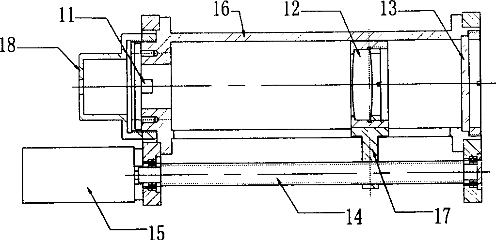
[0032] image 3 It is a specific embodiment of the present invention. The semiconductor laser 1 of this embodiment is fixed on the inner rear end of the lens sleeve 16 by screws, the semiconductor laser 1 itself has been shaped, and the divergence angle is 30°. The double cemented spherical lens 12 has a focal length of 30 mm and a relative aperture of 0.5. It is located inside the lens sleeve 16 and can slide forward and backward therein. The sliding distance is equal to the length of the lens sleeve 16 . The filter protection glass 13 is fixed on the front end of the lens sleeve 16 through a pressure ring. The transmission screw 14 is fixed on the bottom of the lens sleeve 16 through a ball bearing, the right end is connected with the 12V DC motor 15, and the middle is connected with the fixed frame of the doublet lens 12 through the connecting piece 17. The laser protective cover 18 is fixed outside the rear end of the lens sleeve 16 .

[0033] During work, the power lin...


PUM


Abstract

The invention relates to an application technique of semi-conductor laser, especially providing a semi-conductor laser lighting variable-focus device used in remote distance and wide range, wherein the invention comprises a semi-conductor laser; it is characterized in that: the front of laser is arranged with rectify light device, the thin lens group with positive refraction, the rectified light source S at the light axis of thin lens group, and the distance L between thin lens groups between 0 and f, while f is the focus of thin lens group; the lower end of thin lens group is arranged with mechanical transmission device connected to motor. The invention can electrically control the lighting angle and realize wide variation, with small volume and low cost.

Description

(1) Technical field [0001] The invention relates to the application technology of a semiconductor laser, in particular to a zoom device for a long-distance and large-range semiconductor laser illuminator, especially an application device when the laser is used as an illumination light source. (2) Background technology [0002] For devices using semiconductor lasers as lighting sources, the lighting angle is generally fixed. Even if a certain adjustment range is left in the design, the adjustment range is relatively small and is manual. Once the installation is adjusted, it will be completely Fixed dead. In patent Z972157018, the laser illuminator used for the railway locomotive monitor, in order to clearly see the scene signal at 2000 meters, the lighting angle is fixed very small. The laser illuminator products of domestic Beijing Gaobo Video Company and Beijing Coherent Optoelectronics Co., Ltd. have a certain range of adjustment for the illumination angle, but when insta...

Claims


Application Information

Patent Timeline
Patent Type & Authority Applications(China)
IPC IPC(8): G02B7/10H01S5/00
Inventor 张超岳桑建国赵万存杨华军苏明连王连文赵敬伟怀洪波彭媛郭栋
Owner 山东神戎电子股份有限公司
Why Eureka
Try Eureka