
Laser cutter for liquid-crystal screen short-circuit loop

A technology of laser cutting and short-circuit ring, applied in the field of machinery, can solve the problems of low production efficiency and slow cutting speed, and achieve the effect of improving production efficiency, improving cutting and forming speed, and being easy to master and adjust.

Inactive Publication Date: 2007-01-17
CHANGCHUN INST OF OPTICS FINE MECHANICS & PHYSICS CHINESE ACAD OF SCI
View PDF0 Cites 9 Cited by
  • Summary
  • Abstract
  • Description
  • Claims
  • Application Information

AI Technical Summary

Problems solved by technology

[0003] In order to solve the problems of slow cutting speed and low production efficiency of the above-mentioned technology, the purpose of the present invention is to increase the cutting speed and provide a laser cutting equipment for short circuit ring of liquid crystal screen which can meet the requirements of high speed cutting, high production efficiency and compact structure

Method used


Image

  • Laser cutter for liquid-crystal screen short-circuit loop
  • Laser cutter for liquid-crystal screen short-circuit loop
  • Laser cutter for liquid-crystal screen short-circuit loop

Examples


Embodiment Construction

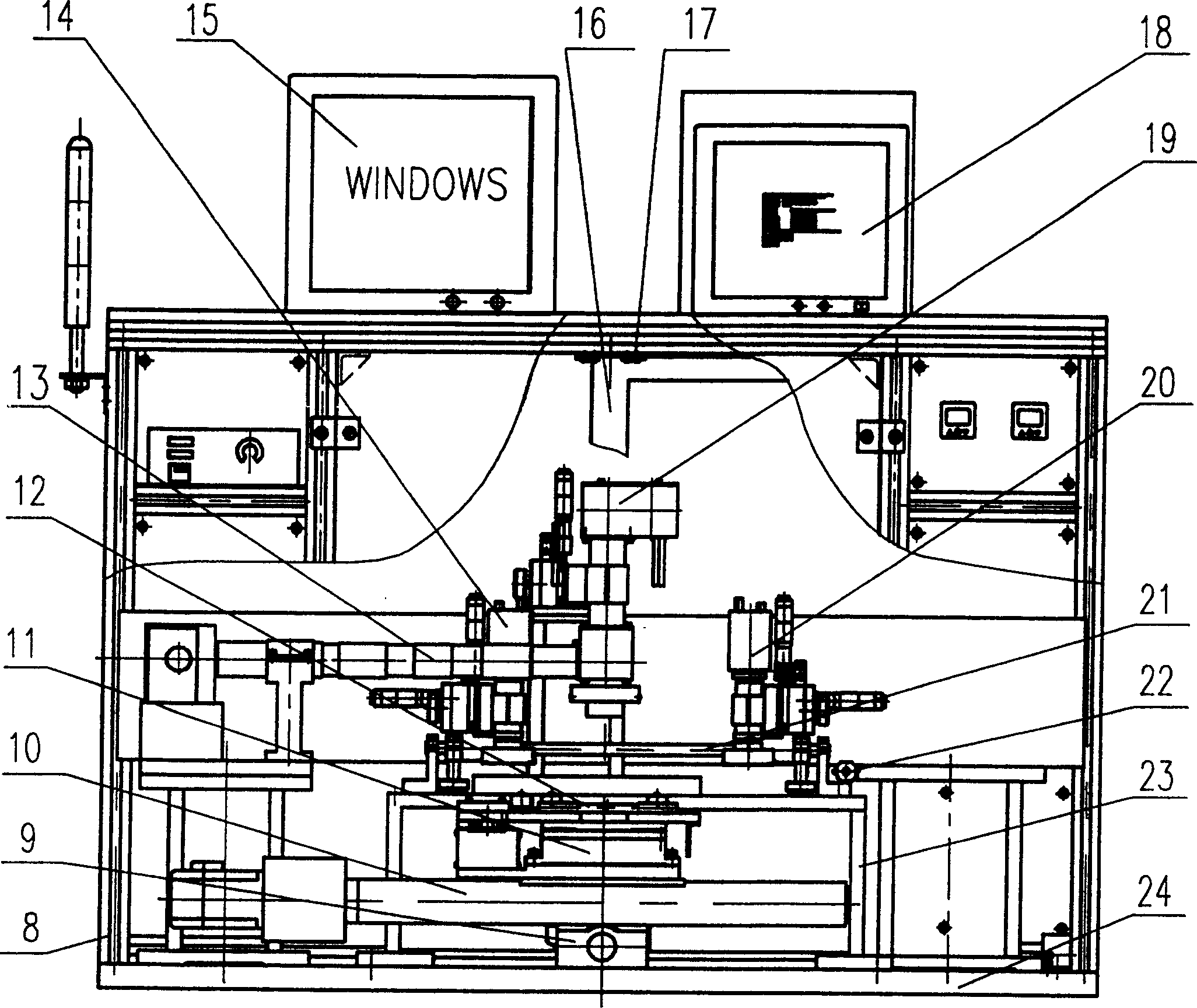
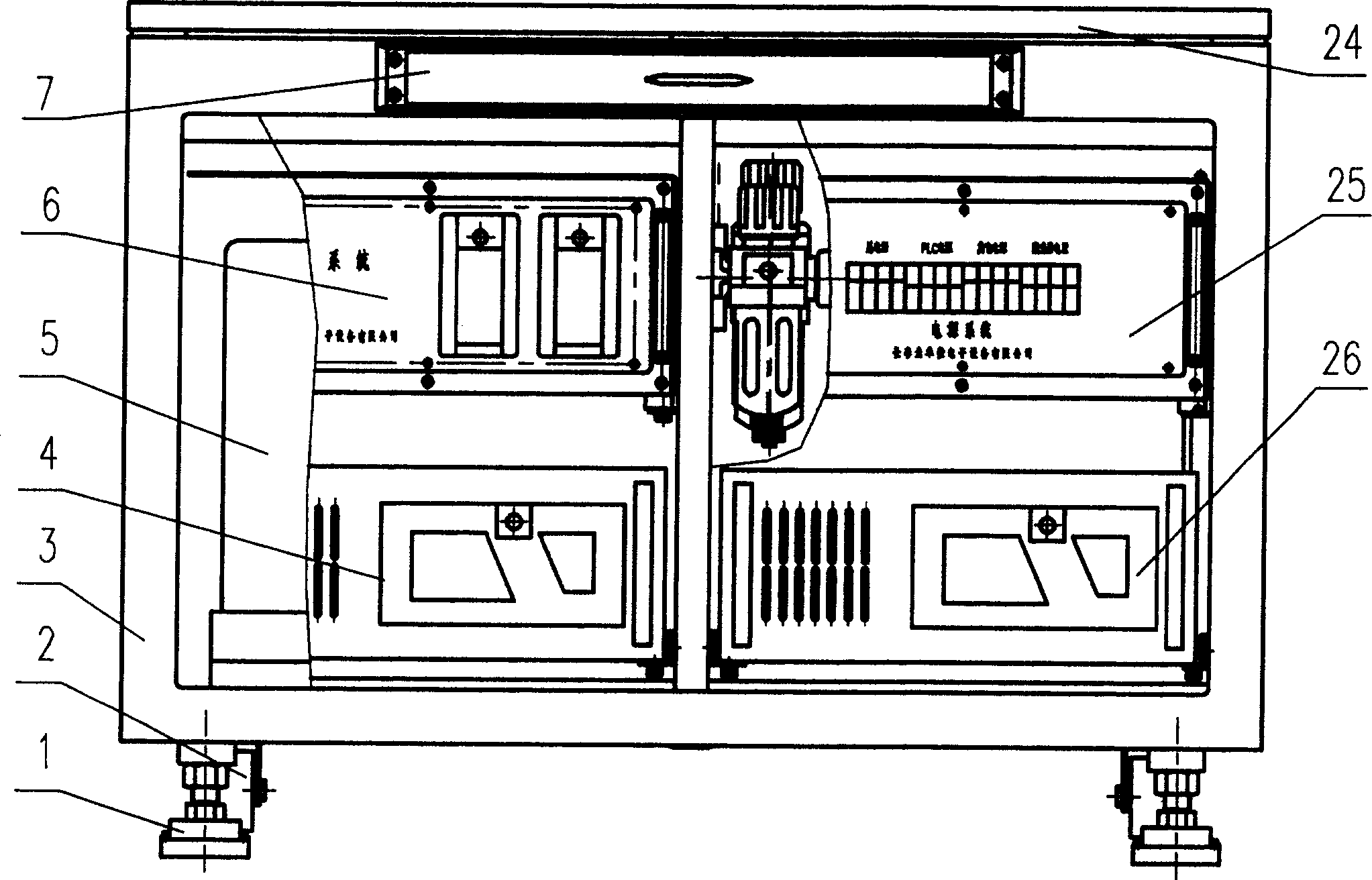
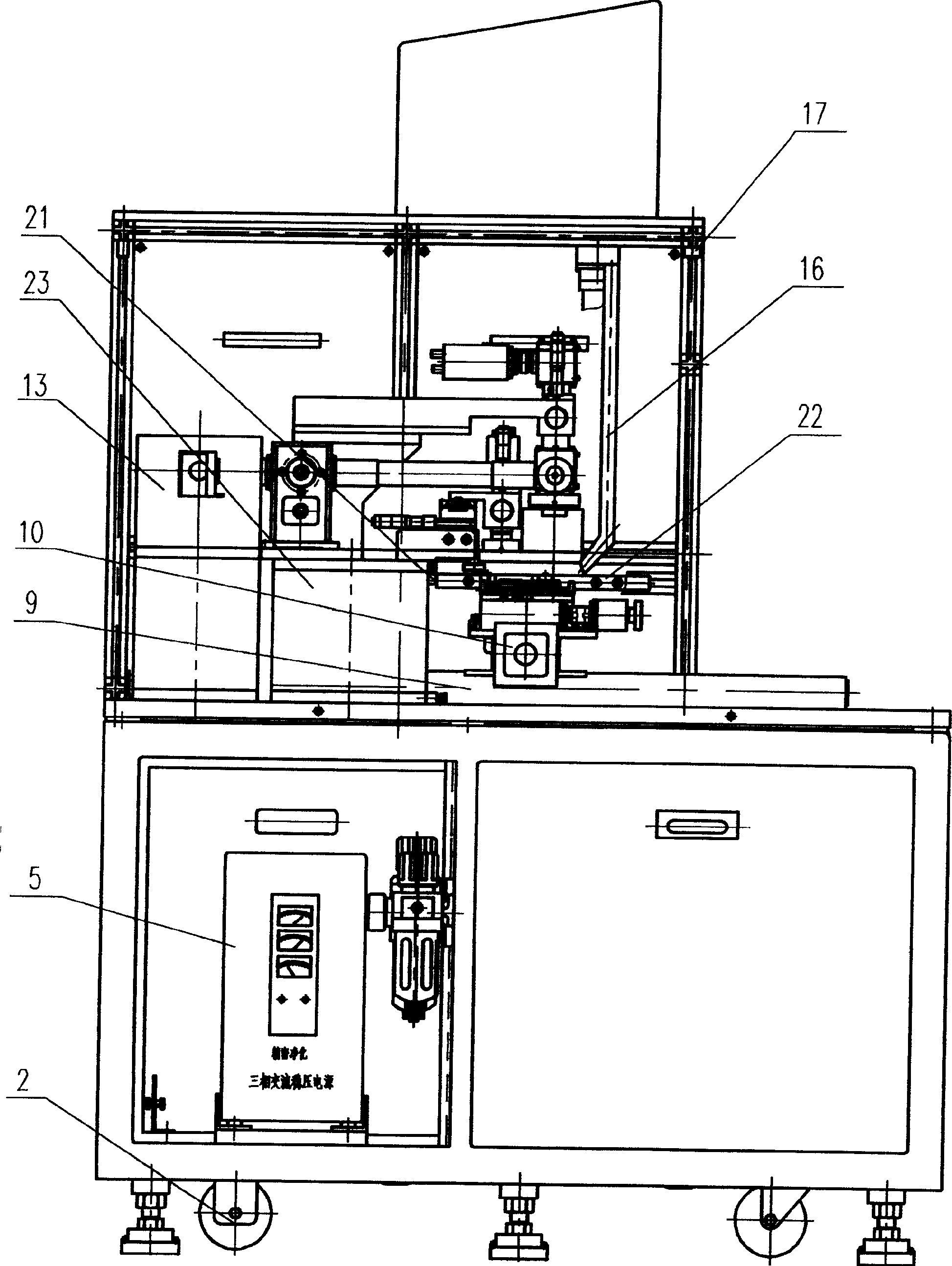
[0017] Such as Picture 1-1 , Figure 1-2 , figure 2 As shown in the preferred embodiment: it includes a leveling mechanism 1, casters 2, lower frame assembly 3, host driver 4, purification power supply 5, motion control system 6, man-machine dialogue device 7, upper frame assembly 8 , Y-axis table 9, X-axis table 10, θ-axis turntable 11, substrate carrier 12, laser cutting system 13, first alignment system 14, main control computer display screen 15, dust suction device 16, switch 17, Image monitor 18, image monitoring system 19, second alignment system 20, static electricity removal device 21, blowing device 22, frame assembly 23, workbench 24, power supply system 25, pneumatic system 26.

[0018] The first alignment system 14, the second alignment system 20, and the image monitoring system 19 all adopt a CCD camera mechanism, which is a product of Mintong Company. Y-axis table 9, X-axis table 10, and θ-axis turntable 11 use high-precision positioning platforms produced b...


PUM


Abstract

A laser cutting apparatus for the short-circuit ring of liquid crystal screen is composed of leveling mechanism, castors, upper and lower machine frame modules, master driver, cleaning power supply, moving control system, man-machine interaction device, Y-axis bench, X-axis bench, theta-axis turntable, basic plate carrier, laser cutting system, the first and the second align systems, display screen of control computer, dusting unit, switch, image monitor, image monitor system, antistatic device, blower, frame module, bench, power supply system, and pneumatic system.

Description

technical field [0001] The invention belongs to the field of machinery, and relates to laser cutting equipment for short-circuit rings of liquid crystal screens, and relates to special optoelectronic equipment for laser cutting short-circuit ring connections around liquid crystal screens. Background technique [0002] The method and device for cutting non-metallic substrates with laser beams, its patent publication number is 1386606, which scans the first laser beam on the path of cutting non-metallic substrates, and the first laser beam is used to break non-metallic substrates Molecular bonds of the material to form a scribe line of a crack with a desired depth; and scanning the second laser beam along the scan path of the first laser beam to propagate the crack in the depth direction of the non-metallic substrate and completely cut the non-metallic substrate . Due to this structure, the object to be cut can be cut twice, so that its cutting speed is slow and the productio...

Claims


Application Information

Patent Timeline
IPC IPC(8): B23K26/00B23K26/04B23K26/08B23K26/16B23K26/42B23K26/38B23K26/70
Inventor 董吉洪徐宏宋云夺
Owner CHANGCHUN INST OF OPTICS FINE MECHANICS & PHYSICS CHINESE ACAD OF SCI
Learn More