

Optical system of small dynamic starlight analog device
An optical system and simulator technology, applied in the field of optical systems, can solve the problems of complex structure, inconvenience and large size of the instrument, and achieve the effects of small size, convenient use and simple structure
Inactive Publication Date: 2007-01-17
CHANGCHUN INST OF OPTICS FINE MECHANICS & PHYSICS CHINESE ACAD OF SCI
View PDF0 Cites 10 Cited by
- Summary
- Abstract
- Description
- Claims
- Application Information
AI Technical Summary
Problems solved by technology
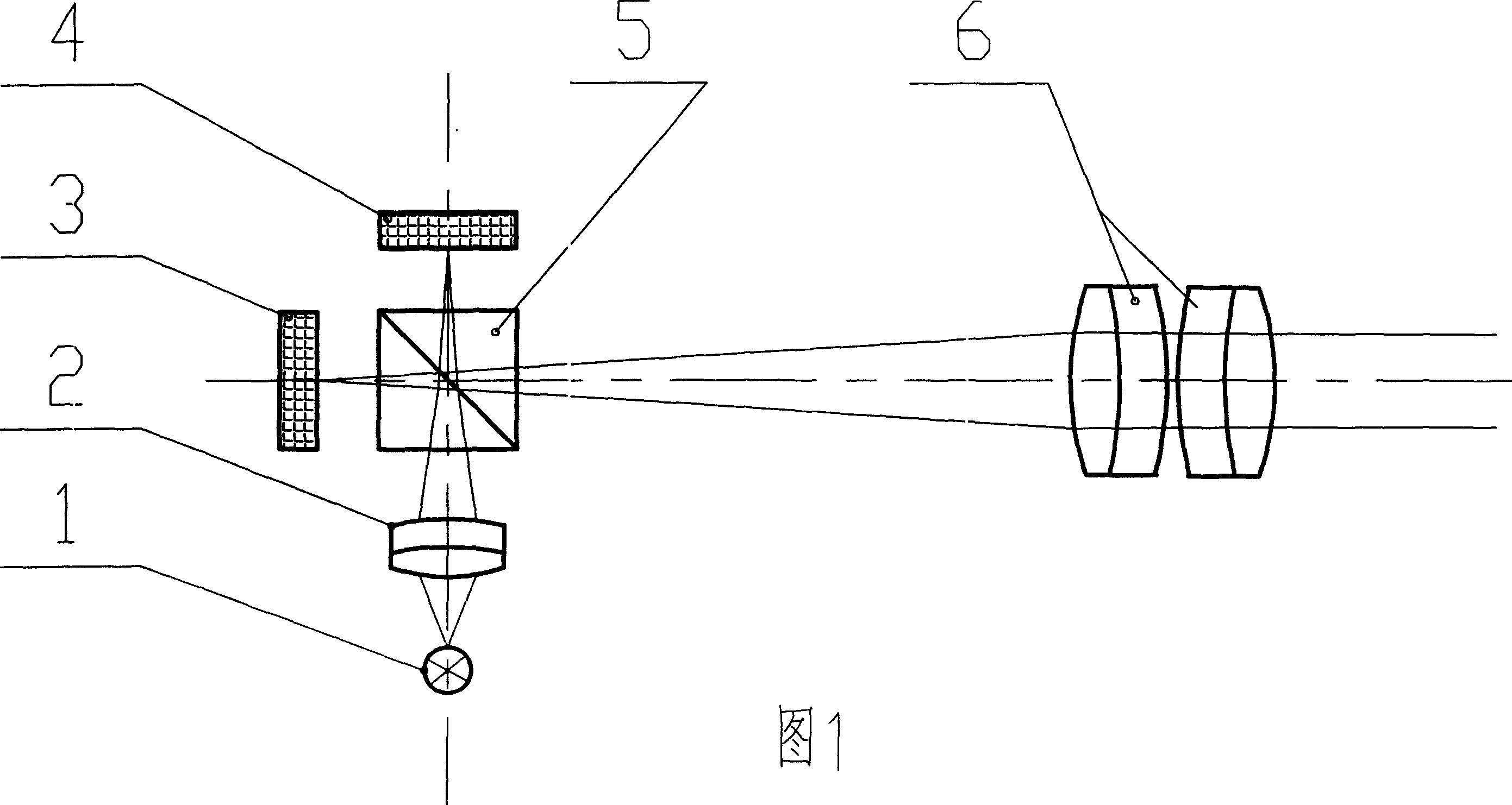
[0005] The main problem of the optical system of this small dynamic simulator is: in order to obtain the star map with ideal resolution, two liquid crystal light valves need to be used to splice the field of view, and the illumination part also needs to use glued prisms, resulting in complex structure and large volume of the instrument , heavy weight, not easy to use
Method used
View moreImage
Smart ImageViewing Examples

Examples
Embodiment Construction
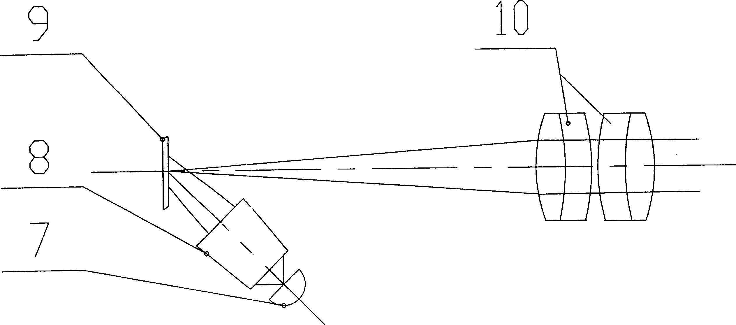
[0013] The invention according to figure 2 The structure shown is implemented where:
[0014] The light source 7 adopts bromine tungsten lamp;
[0015] Illumination optical lens 8 adopts Kolar illumination system to ensure uniform illumination of DMD;
[0016] Digital Microchip (DMD) 9 adopts the patented product DMD chip of Texas Instruments (T1);
[0017] The collimating objective lens group 10 adopts an apochromatic and Petzval flat field curvature collimating objective lens.
Login to View More PUM
 Abstract
A kind of optical system of the minitype dynamic starlight simulator belongs to the space detecting technique field. It includes a lamp-house, a illuminating optical lens, a digital minicrystal and a collimating objective group. The digital minicrystal and the collimating objective group are set at the ray axis of the horizontal beam path. The reflecting surface of the digital minicrystal is towards the collimating objective group and on the focal surface of it. The beam path axis composed of the lamp-house and the illuminating optical lens forms certain angle with the horizontal beam path axis and its extension line goes through the center of the digital minicrystal. The lamp-house emits uniform light through the illuminating optical lens and the light is reflected by the digital minicrystal and is sent out by the collimating objective group along the horizontal ray axis. The structure of the optical system is simple; the volume is small; the weight is light. And it is applied conveniently.
Description
1. Technical field [0001] The invention belongs to an optical system of a starlight simulator related to the technical field of space detection. 2. Technical background [0002] Meteorological satellites, communication satellites, lunar exploration projects and other spacecraft are equipped with starlight sensors to track stars pointing to a certain magnitude to determine the on-orbit attitude of the spacecraft. Therefore, before these spacecraft are launched, they need to perform a star-following test on the starlight sensor on the ground. The starlight simulator can simulate stars of various magnitudes, providing the necessary test conditions, and the optical system of the starlight simulator is its core. [0003] At present, developed countries, especially aerospace developed countries, are developing and producing starlight simulators and starlight sensors. Since these technologies are all high-tech, the countries concerned have strictly blocked them from the outside w...
Claims
Login to View More Application Information
Patent Timeline
 Patent Type & AuthorityApplications(China)
IPC IPC(8): G02B27/00G01M19/00G09B9/00G01M99/00
Inventor巩岩
OwnerCHANGCHUN INST OF OPTICS FINE MECHANICS & PHYSICS CHINESE ACAD OF SCI