
Spatial division multiplexing for mimo devices

A space, complex conjugate technology, applied in the field of information communication, can solve problems such as increased cost and maintenance problems, and achieve the effect of less processing

Inactive Publication Date: 2007-01-17
KK TOSHIBA
View PDF0 Cites 3 Cited by
  • Summary
  • Abstract
  • Description
  • Claims
  • Application Information

AI Technical Summary

Problems solved by technology

This is particularly evident in systems that require three transmit antennas for capacity reasons, where the additional antennas, bringing the total to four, represent a 33% increase in hardware in terms of associated costs and maintenance issues

Method used


Image

  • Spatial division multiplexing for mimo devices
  • Spatial division multiplexing for mimo devices
  • Spatial division multiplexing for mimo devices

Examples


Embodiment Construction

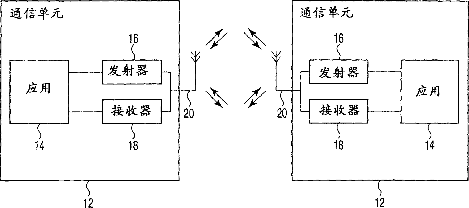
[0046] first reference figure 1 , the figure illustrates a communication system 10, which in this example includes two communication units 12 for convenience. Each communication unit 12 includes one or more application units 14 in communication with a transmitter 16 and a receiver 18 . The transmitter 16 and receiver 18 are considered to be in communication via an antenna unit 20 comprising a plurality of antenna elements to enable multiple-input multiple-output (MIMO) communication with other communication units 12 . The system 10 is in a diffuse environment such that multiple paths can be advantageously employed for communication between the two described communication units 12 .

[0047] In use, the application 14 would pass data for transmission to the transmitter 16, which would then process the data and drive the antenna unit 20 to create an electromagnetic radiation that could then be communicated by another detected by antenna unit 20 of unit 12.

[0048] When elect...


PUM


Abstract

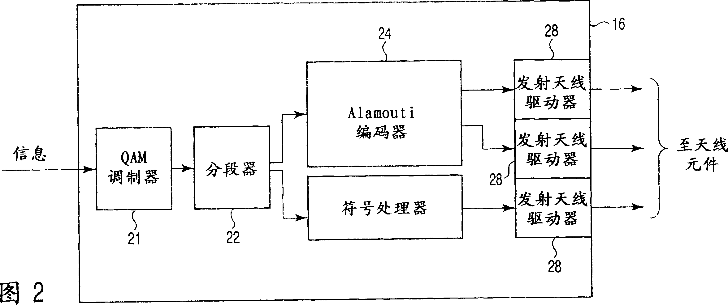
A communications system, comprising a transmitter and a receiver, are operable to communicate information using a spatial multiplexing method. The transmitter is operable to separate data to be transmitted into two categories, Alamouti encoding the symbols of the first category and transmitting them on an even number of antennae, and not encoding the second category of symbols, but merely using a modulation scheme such as QAM, and transmitting them on one or more further antennae. A corresponding receiver is operable to successively detect signal components received on corresponding spatially displaced antennae, and then to determine an estimated channel response from the signal components. A weighting function is then derived to extract a stream of data from the received signal, which, on the basis that the Alamouti STBC encoded signal will have the highest signal to noise ratio, will normally be the latter, while other data not encoded according to Alamouti is detected thereafter.

Description

technical field [0001] The present invention relates to information communication in wireless communication systems using space division multiplexing in multiple-input, multiple-output (MIMO) devices. Background technique [0002] A common method of transmitting data for multiple antennas is to use a space-division multiplexing process, notably a method known as V-BLAST, which is described in "V-BLAST: an architecture for realizing very high data rates over the rich- scattering wireless channel” (Wolniansky, P.W.; Foschini, G.J.; Golden, G.D.; Valenzuela, R.A: 1998 URSI International Symposium on Signals, Systems, and Electronics, 1998; ISSSE 98., 29Sept.-2Oct.1998, pp.295-300) [0003] In V-BLAST, each transmit antenna (Tx) includes a conventional quadrature amplitude modulation (QAM) modulator. Receivers can employ an ordered sequential interference cancellation (OSIC) algorithm coupled with zero-forcing (ZF) or with minimum mean square error (MMSE) to spatially separate ...

Claims


Application Information

Patent Timeline
IPC IPC(8): H04L1/06H04B7/06H04B7/08H04J99/00H04B7/04H04L1/00
CPCH04B7/0697H04L1/0656H04L1/0631H04L2001/0098H04B7/04H04L1/0625H04L1/0668
Inventor 孙勇陈华勋
Owner KK TOSHIBA
Learn More