Spiral structure type osteo-tooth implant coated with nano-apatite layer

A technology of helical structure and implant, applied in the direction of dental prosthesis, dentistry, implant, etc., can solve the problems of implant loosening and coating damage, and achieve the effect of improving occlusal force, expanding range and improving contact rate.

Inactive Publication Date: 2007-01-31
ZHEJIANG UNIV
View PDF0 Cites 6 Cited by
  • Summary
  • Abstract
  • Description
  • Claims
  • Application Information

AI Technical Summary

Problems solved by technology

The detection of failed implants found that the accumulation of disintegrated coating material particles around the implant can stimulate various phagocytic responses, cause the secretion of various cytokines

Method used


Image

  • Spiral structure type osteo-tooth implant coated with nano-apatite layer

Examples


Embodiment Construction

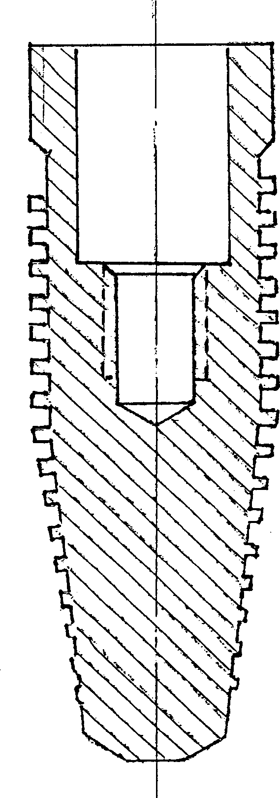
[0011] refer to figure 1 , the nano-apatite-coated helical dental bone implant of the present invention is shaped like a bullet, 1 / 2 of which is a cylinder, and the other 1 / 2 of which is a cone, and the taper of the cone is generally 1-2. 30°, the implant has an external thread, and the cross-section of the thread is rectangular; the outer surface of the implant is coated with nano-apatite, and there is a stepped hole on the axis of the cylinder for connecting with the operating abutment. The small diameter section of the stepped hole has an internal thread.

[0012] The implant implant body of the present invention can be made of pure titanium or titanium alloy.

[0013] Tests have shown that, in terms of bone mass, the lower bone section diameter of the implant implant of the present invention can be reduced by 2mm compared with the columnar implant, and the amount of bone loss is significantly reduced. In terms of bone quality, the elastic modulus of cortical bone can be ...


PUM

PropertyMeasurementUnit
Taperaaaaaaaaaa

Abstract

An implant for transplanting tooth bone in it has a bullet-like shape, cylindrical upper half, conic lower half, external spiral thread, coated nano-apatitie layer on its external surface, and axial stepped internal hole with internal spiral thread on the inner surface of small-diameter segment.

Description

technical field [0001] The invention relates to a nano-apatite-coated helical bone-tooth implant for bone and tooth restoration, belonging to the field of bone and oral surgery implants. Background technique [0002] Since T. Steele officially proposed the concept of bionics in 1960, bionic research has gradually been used in the preparation of artificial biological composite materials to improve bionics and improve the overall performance of biomaterials. The current international mainstream bone implant system is bioactive bone implant material coated with hydroxyapatite (HA) (plasma spraying); dental implants mainly include Branemark, Frialit-2, Astra, Replace, ITI, Biohorizons, etc. (see: JP Geng, KB Tan, GR Liu. Application of finiteelement analysis in implant dentistry: a review of the literature. JProsthet Dent, 2001; 85(6):585-98). Among them, the columnar spiral implant and Replace represented by Branemark, and the root implant represented by Frialit-2 are the most...

Claims


Application Information

Patent Timeline
IPC IPC(8): A61C8/00A61K6/04A61K6/033A61K6/838
Inventor 严伟琪耿建平
Owner ZHEJIANG UNIV
Why Eureka
Try Eureka