Heat exchanger, in particular a flat pipe evaporator for a motor vehicle air conditioning system

A technology for heat exchangers and automotive air conditioners, applied in heat exchange equipment, heat exchange equipment safety devices, heat exchanger types, etc., can solve problems affecting evaporator water storage and discharge performance, and reduce the risk of sudden fog formation, The effect of reducing the risk of bacterial growth and reducing the generation of odor

Inactive Publication Date: 2007-02-14
BEHR GMBH & CO KG
View PDF1 Cites 13 Cited by
  • Summary
  • Abstract
  • Description
  • Claims
  • Application Information

AI Technical Summary

Problems solved by technology

[0009] For example, due to the existing fin shape, the fins in the evaporator are almost parallel or the opening angle between the fin segments is small, which affects the water storage and discharge performance of the evaporator

Method used


Image

  • Heat exchanger, in particular a flat pipe evaporator for a motor vehicle air conditioning system
  • Heat exchanger, in particular a flat pipe evaporator for a motor vehicle air conditioning system
  • Heat exchanger, in particular a flat pipe evaporator for a motor vehicle air conditioning system

Examples


Embodiment Construction

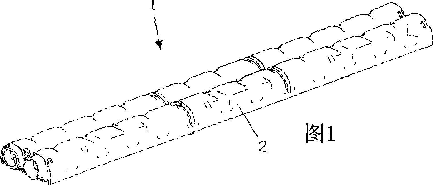
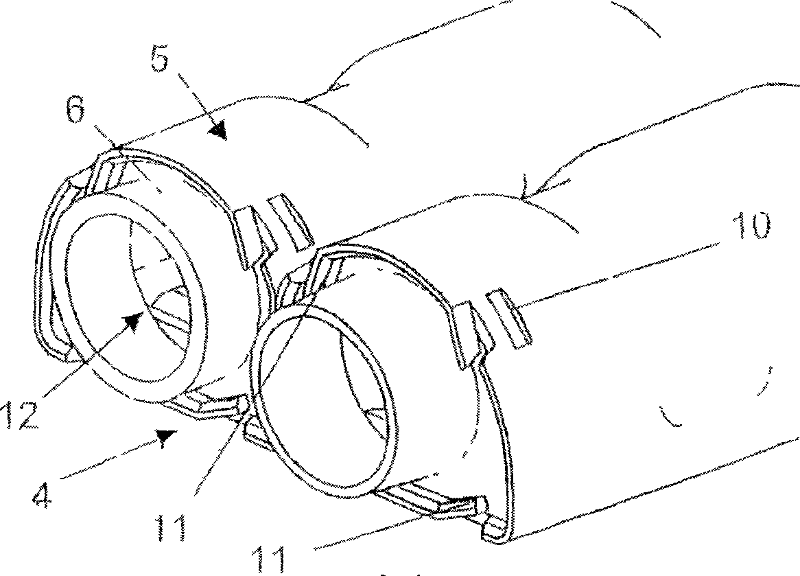
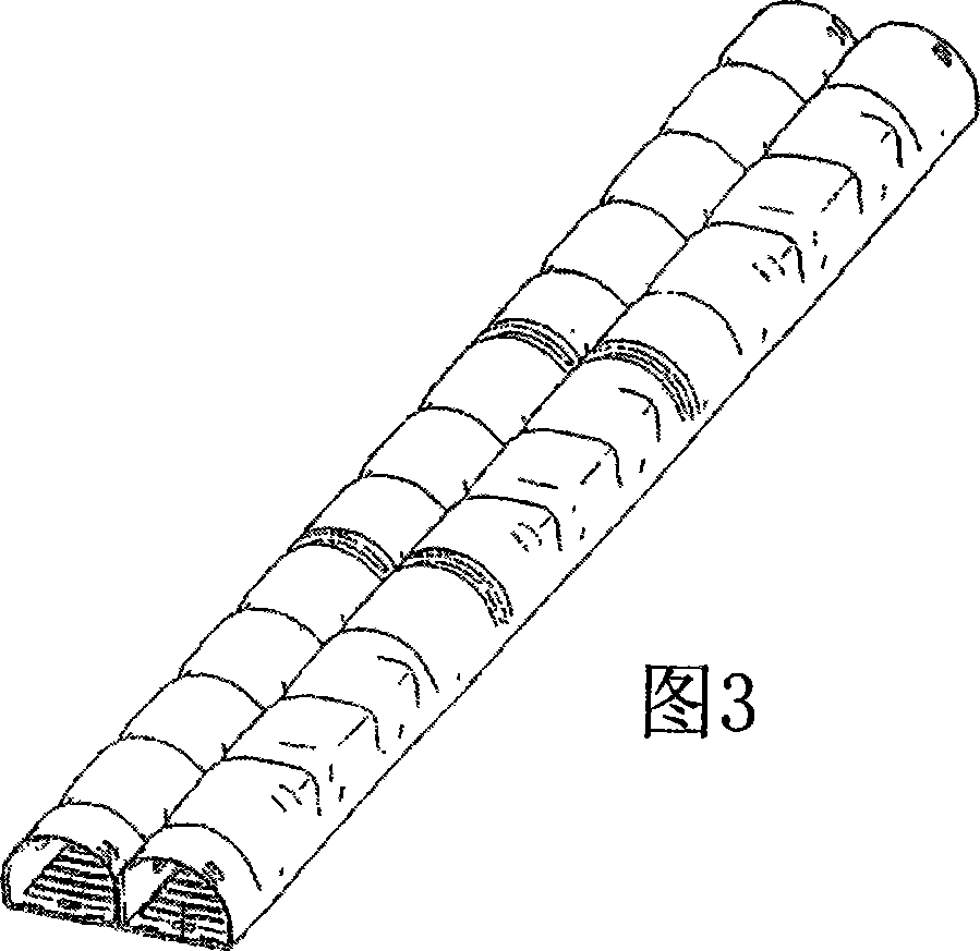
[0045] As previously described in DE198 26 881A1, the flat tube evaporator 1 (only a part in the figure) of the automobile air-conditioning equipment includes two collecting tanks 2, a flat tube (not shown) between the two collecting tanks 2 and Corrugated fins 3 arranged between flat tubes. According to this embodiment, each collecting tank 2 is formed by a slab stamped from sheet material, and the slab forms a flat collecting tank part 4 and two tunnel-shaped Collecting box part 5 (see Figure 4 and 6). Its longitudinal edge is provided with a plurality of tabs distributed over its length, which are inserted into openings in the flat collecting tank part 4 and caulked on the outside facing the flat tube. The ends are closed by caps 6 which will be described in detail later.

[0046] Formed in the flat collecting tank part 4 are a plurality of flanged holes 7 into which the flat tubes are inserted, wherein the shape of the openings of the flanged holes 7 substantially corr...


PUM


Abstract

A collecting tank (2) divides lengthwise into two chambers. Ends of pipes, e.g. flat pipes, are inserted into the base of the collecting tank, which has a tunnel-shaped collecting tank part, i.e. a level collecting tank part to form the base, and covers at each front side. - An INDEPENDENT CLAIM is also included for a motor vehicle's air-conditioning facility with a vaporizer.

Description

technical field [0001] The invention relates to a heat exchanger, in particular to a flat tube evaporator used in an automobile air conditioner. Background technique [0002] DE 198 26 881 A1 discloses a heat exchanger, in particular an evaporator, in which a collecting tank made of sheet metal is provided, which is formed from a prefabricated blank. [0003] The plate blank consists of an aluminum alloy which also forms the flat tubes, corrugated fins and side parts and other elements of the heat exchanger. The slab is first stamped from a single plate and then shaped to form a flat base (essentially flat header tank part) and a curved part (tunnel-shaped header tank part) parallel to its longitudinal sides catch. The curved member is curved according to a radius into a cylindrical surface, and the longitudinal edges of the cylindrical surface are bent so that the edges are parallel to each other and close together, and substantially perpendicular to the base. The longit...

Claims


Application Information

Patent Timeline
Patent Type & Authority Applications(China)
IPC IPC(8): F28F9/02F28D1/053F28F1/12F28F9/04
CPCF28F2265/32F28F2220/00F28D1/05366F28F9/0246F28F9/0204F28D2021/0085F28F1/126
Inventor 戈特弗里德·迪尔克劳斯·弗尔斯特米夏埃尔·科尔埃米尔·诺伊曼弗朗茨·奥托沃尔夫冈·泽瓦尔德
Owner BEHR GMBH & CO KG
Why Eureka
Try Eureka