Technique for strengthening boundary face of functional gradient material of shield duct piece by using FRP rib

A technology of functionally graded materials and shield segments, which is applied in the direction of structural elements, building components, manufacturing tools, etc., to achieve the effects of convenient construction, improved bonding strength, and saving procedures

Inactive Publication Date: 2007-02-21
WUHAN UNIV OF TECH
View PDF0 Cites 7 Cited by
  • Summary
  • Abstract
  • Description
  • Claims
  • Application Information

AI Technical Summary

Problems solved by technology

[0004] At present, the application of FRP bars to underground engineering tunnel segments and the strengthening of the functi

Method used


Image

  • Technique for strengthening boundary face of functional gradient material of shield duct piece by using FRP rib
  • Technique for strengthening boundary face of functional gradient material of shield duct piece by using FRP rib
  • Technique for strengthening boundary face of functional gradient material of shield duct piece by using FRP rib

Examples


Embodiment 1

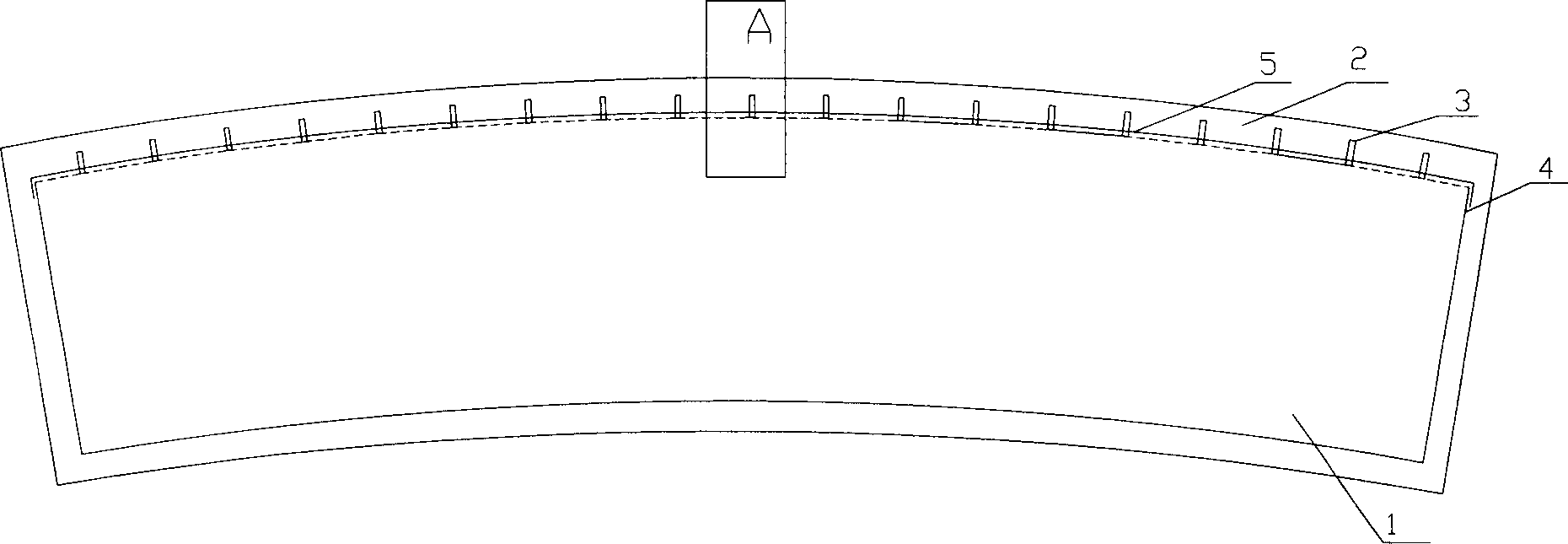
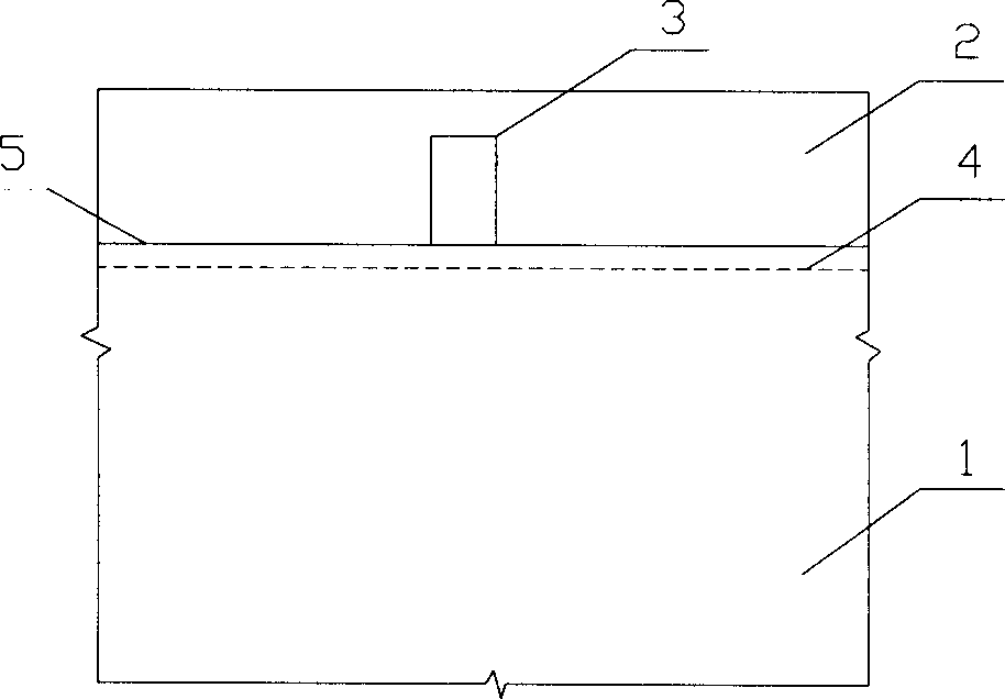
[0023] Such as figure 1 , figure 2 , image 3 As shown, a process of using FRP bars to strengthen the functionally graded material interface of the shield segment. The interface between the reinforced concrete structure layer 1 and the high impermeability protection layer 2 of the shield tunnel concrete segment is a functionally graded material interface. Including the following steps:

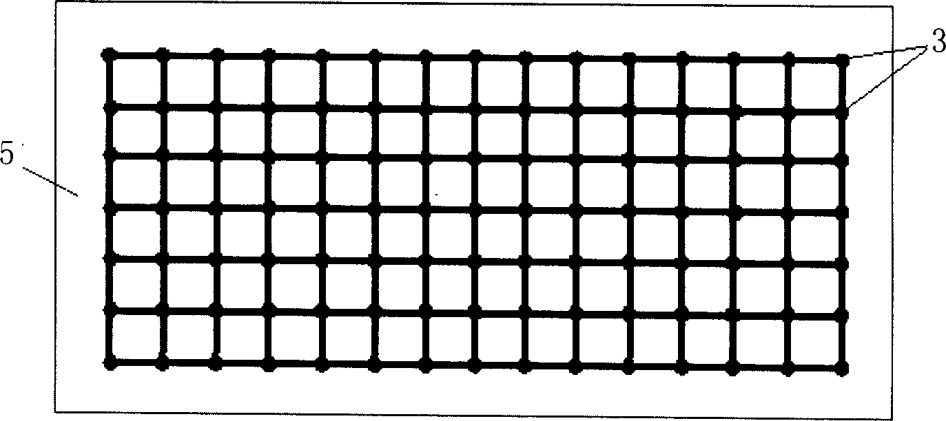
[0024] 1) Establish the FRP tendon anchoring and strengthening transition zone: FRP tendons 3 and flexible FRP mesh cloth 5 are combined to form the FRP tendon interface anchoring reinforcement material, and the preparation process of FRP tendons 3 and flexible FRP mesh cloth 5 is prefabricated in the factory and mass-produced , can be used directly in the preparation process of the shield segment, so as not to affect the construction progress; the outer surface of the FRP reinforcement is a threaded structure, with a diameter of 20mm and a length of 30mm. The spacing between adjacent FRP ...

Embodiment 3

[0043] Such as figure 1 , figure 2 , image 3 Shown, a kind of technology that utilizes FRP rib to strengthen the functionally graded material interface of shield segment, it comprises the following steps:

[0044] 1) Establish the anchoring and strengthening transition zone of FRP tendons: the outer surface of FRP tendons is a threaded structure with a diameter of 30 mm and a length of 40 mm. The distribution of FRP tendons on the grid cloth is distributed in a lattice, and the distance between two adjacent FRP tendons is: 90mm.

[0045] Before the concrete is poured, the flexible FRP grid cloth 5 is laid and pasted on the steel cage surface 4 in the reinforced concrete segment steel mold, and the FRP bars 3 are distributed on the flexible FRP mesh cloth 5 in a lattice shape to form the FRP bar anchoring strengthening transition area, in which FRP tendons (3) and FRP mesh cloth (5) are bonded to form an integral structure, which is completed through factory prefabrication...


PUM

PropertyMeasurementUnit
Diameteraaaaaaaaaa
Lengthaaaaaaaaaa
Particle sizeaaaaaaaaaa

Abstract

The present invention relates to a technical process for reinforcing functional gradient material interface of shield-driven tunnel concrete segment by utilizing FRP rib. Said technical process includes the following steps: (1), creating FRP rib anchorage reinforcement transition zone; laying and sticking flexible FRP mesh fabric on the surface of reinforcing cage in reinforced concrete segment steel mould, on the mesh fabric distributing FRP ribs according to the point lattice form to form FRP rib anchorage reinforcement transition zone, in which the FRP ribs and FRP mesh fabric are adhered together and formed into an integral structure; (2), in the reinforced concrete segment steel mould pouring the high-performance concrete whose strength grade is greater than C50 to upper surface of reinforcing cage to form reinforced concrete structure layer; and (3), utilizing pumping process to pour high-antipermeable protective concrete to surface of steel mould on the reinforced concrete structure layer to form high-antipermeable protective layer.

Description

technical field [0001] The invention relates to a technology for strengthening the functionally gradient material interface of a concrete segment of a shield tunnel by using FRP tendons. Background technique [0002] Compared with the industrial and civil building structures in the atmospheric environment, the operating environment of underground engineering tunnels has more complex factors affecting the durability of structures, and is often subject to the interaction of various damage factors. Therefore, the concrete segments of shield tunnels (or Called shield segment, or shield tunnel segment) performance puts forward higher requirements. Introducing the design principle of functionally graded materials, layered design and multiple pouring of concrete materials used in shield tunnel concrete segments (a functionally graded material interface is formed between layers), can greatly optimize the shield tunnel concrete segments Performance greatly enhances the durability of...

Claims


Application Information

Patent Timeline
IPC IPC(8): E21D11/04E04C5/07
CPCB28B23/02
Inventor 马保国高英力王信刚王凯金宇罗忠涛
Owner WUHAN UNIV OF TECH
Why Eureka
Try Eureka