Device and method for mapping the distribution of an x-ray fluorescence marker

A technology of markers and X-rays, applied in the direction of material analysis, measuring devices, and analysis materials using wave/particle radiation, which can solve problems such as unusable and unobtainable reference volumes

Inactive Publication Date: 2007-02-28
KONINKLIJKE PHILIPS ELECTRONICS NV
View PDF1 Cites 4 Cited by
  • Summary
  • Abstract
  • Description
  • Claims
  • Application Information

AI Technical Summary

Problems solved by technology

However, this method cannot be used when examining a patient, as a reference volume without XRF markers is not available in this case

Method used


Image

  • Device and method for mapping the distribution of an x-ray fluorescence marker
  • Device and method for mapping the distribution of an x-ray fluorescence marker
  • Device and method for mapping the distribution of an x-ray fluorescence marker

Examples


Embodiment Construction

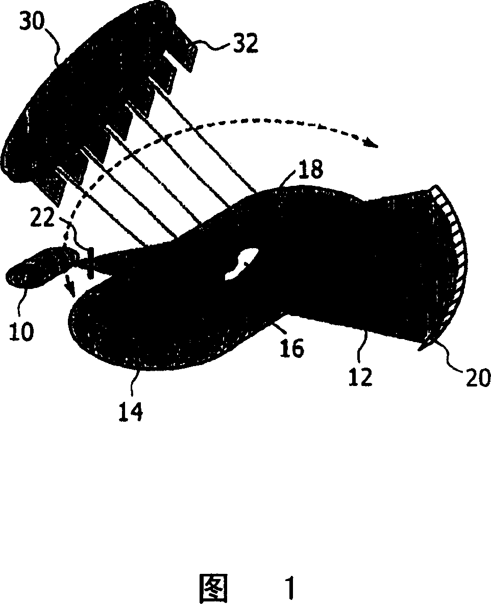
[0031] Using the device shown in FIG. 1 , a morphological image of a body volume 14 and a molecular image of the distribution of XRF markers 16 in said volume 14 can be produced simultaneously. For this reason, the device comprises an X-ray source 10, such as the Flour'X device available from Panalytical, in which the target is impinged by an electron beam. The target then emits X-ray radiation with the source 10 acting as a fan beam 12 . After passing through the body 14, the beam 12 encounters a linear transmission detector 20 for position-resolved measurement of the radiation intensity arriving there. In this way, an X-ray projection can be produced, in which each image point on the transmission detector 20 exhibits an overall X-ray absorption in the body 14 along the line from the image point to the radiation source 10 .

[0032] The body volume 14 also includes a distribution of XRF-emitting XRF markers 16 excited by the primary radiation of the radiation beam 12 . In o...


PUM


Abstract

The invention relates to a method and a device for determining the distribution of an X-ray fluorescence (XRF) marker (16) in a body volume (14). The body volume (14) is irradiated with a beam of rays (12) from an X-ray source (10) with a first ray component with a quantum energy just above and a second ray component with a quantum energy just below the K-edge of the XRF marker (16). Secondary radiation emitted from the body volume (14) is detected in a location-resolved way by a detector (30). To separate the X-ray fluorescence components in the secondary radiation from background radiation, the body volume is irradiated for a second time with a beam of rays from which the first ray component has been substantially removed by a filter (22) made from the material of the XRF marker.

Description

technical field [0001] The present invention relates to methods and devices for mapping the distribution of X-ray fluorescent markers in a body volume, wherein the fluorescence of the markers is excited by an X-ray source. Background technique [0002] Methods for molecular imaging have been described in the literature, where X-ray fluorescence emission of atoms with higher atomic numbers complexed with drugs is indicated (Takeda et al. entitled "Fluorescent scanning X-ray tomography with synchrotronradiation" , 1995, Rev. Sci. Instrum. Vol. 66, pp. 1471-1473). X-ray fluorescence (XRF) occurs when electrons from a higher energy quantum level fall on the position of a lower quantum level, which is preceded by primary X-rays with sufficiently high quantum energy. freed. Since the spectrum of emitted XRF photons is characteristic of the emitting element and the intensity of the spectral lines is proportional to the mass of the XRF marker, even the spatial distribution of mark...

Claims


Application Information

Patent Timeline
Patent Type & Authority Applications(China)
IPC IPC(8): G01N23/223
CPCG01N23/223G01N2223/076G01N2223/0766
Inventor G·哈丁G·马滕斯H·巴施多夫B·施维策尔
Owner KONINKLIJKE PHILIPS ELECTRONICS NV
Why Eureka
Try Eureka