An anode in a field emission light source and a field emission light source comprising the anode

A technology of emitting light source and anode, applied in the direction of electron emission electrode/cathode, fluorescent screen lamp, gas discharge lamp parts, etc., can solve the problems of charge accumulation, complex manufacturing, energy loss of emission light source, etc.

Inactive Publication Date: 2007-02-28
LIGHTLAB SWEDEN AB
View PDF2 Cites 8 Cited by
  • Summary
  • Abstract
  • Description
  • Claims
  • Application Information

AI Technical Summary

Problems solved by technology

For example, field emission light sources of the type described above may cause energy losses in conductive materials due to absorption
There is also a risk of charge build-up
Furthermore, the manufacture of light sources of the type mentioned above is a rather complicated matter

Method used


Image

  • An anode in a field emission light source and a field emission light source comprising the anode
  • An anode in a field emission light source and a field emission light source comprising the anode
  • An anode in a field emission light source and a field emission light source comprising the anode

Examples


Embodiment Construction

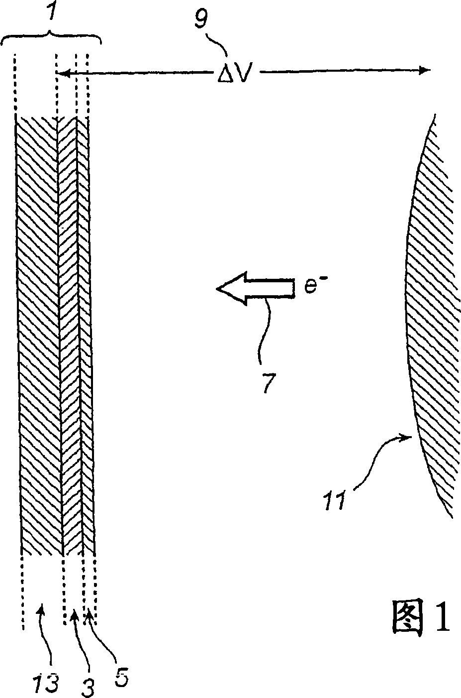
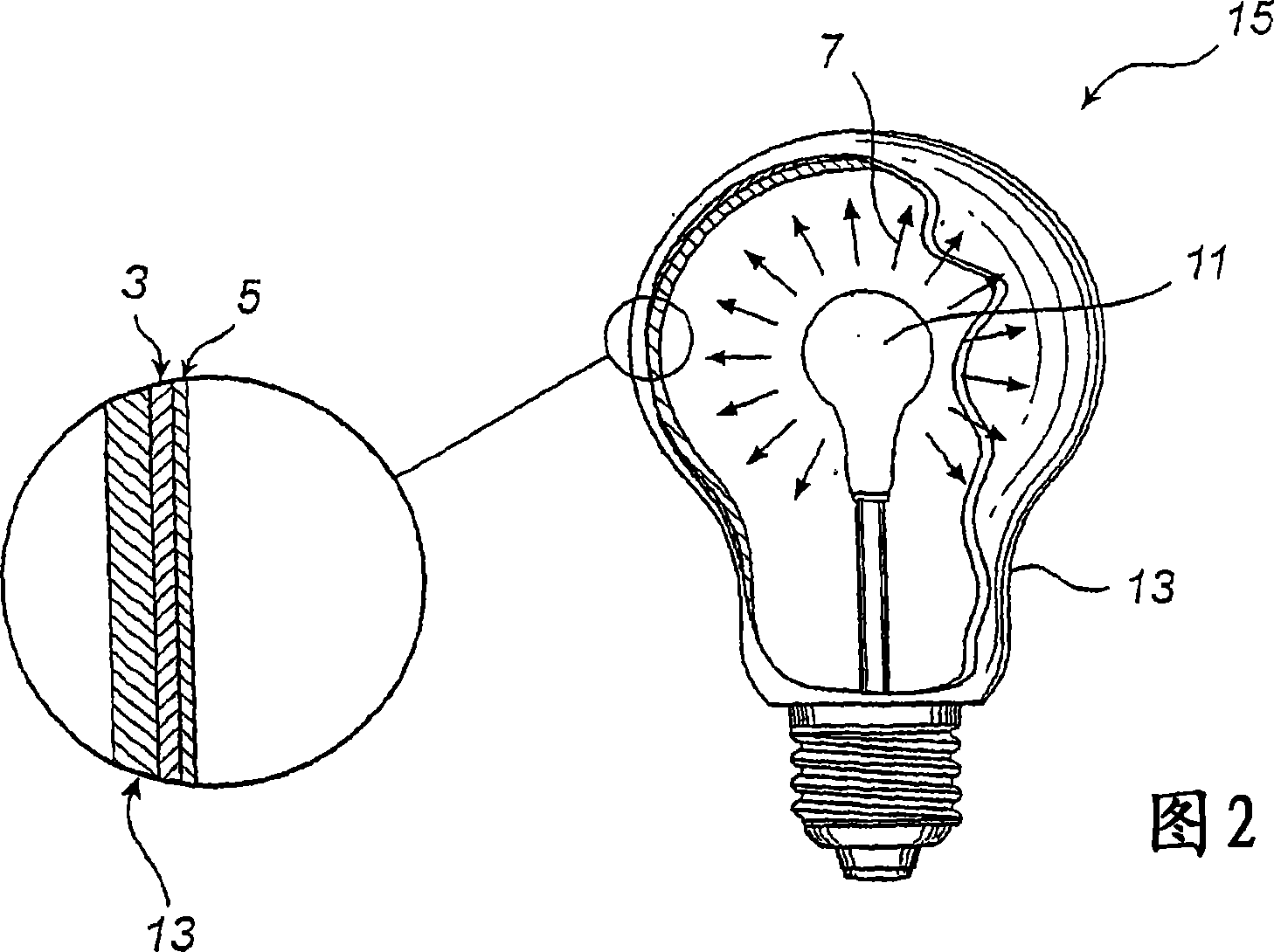
[0023] In Fig. 1 an embodiment of an anode 1 in a field emission light source according to the invention is disclosed. The anode 1 comprises a conductive layer 3 and a light-emitting layer 5 that emits light when excited by electron bombardment 7 caused by a potential difference 9 between the conductive layer 3 and the cathode 11 . The light emitting layer 5 is disposed between the conductive layer 3 and the cathode 11 . The conductive layer 3 is a transparent conductive layer 3 . The light-emitting layer 5 directly adjoins the transparent conductive layer 3 . The thickness of the transparent conductive layer 3 is 100-1000 nm, more preferably 400-600 nm and still more preferably 450-550 nm. The potential difference 9, ΔV is 4-12KV, and more preferably 5-11KV.

[0024] In one embodiment the transparent conductive layer is indium tin oxide (ITO) and in another embodiment the transparent conductive layer is zinc oxide (ZnO).

[0025] In this particular embodiment, the anode 1...


PUM


Abstract

An anode (1) in a field emission light source (15) is disclosed. The anode (1) comprises an electrically conductive layer (3) and a luminescent layer (5) that is luminescent when excited by electron bombardment (7) caused by a potential difference (9) between the electrically conductive layer (3) and a cathode (11). Key features are that the luminescent layer (5) is arranged between the electrically conductive layer (3) and the cathode (11) and that the electrically conductive layer (3) is a transparent electrically conducting layer (3). Further, a field emission light source (15) comprising the anode (1) is also disclosed.

Description

technical field [0001] According to a first aspect, the invention relates to an anode in a field emission light source. [0002] According to a second aspect, the invention relates to a field emission light source comprising such an anode. Background technique [0003] In US 5,877,588 a light source is disclosed comprising a vacuum container having a peripheral wall at least partly composed of an outer glass layer on which at least one of them is covered on the inside with a layer of phosphor forming a luminescent layer. The main components. The conductive layer constitutes the anode. The phosphor layer is excited to emit light by electron bombardment from a field emission cathode located inside the container and a modulating electrode or grid arranged between the cathode and the anode for forming an electric field for emitting electrons. The field emission cathode includes some field emitters in the form of fibers and a base frame with longitudinally extending core wires...

Claims


Application Information

Patent Timeline
Patent Type & Authority Applications(China)
IPC IPC(8): H01J61/04H01J19/02H01JH01J63/02H01J63/06
CPCH01J63/02H01J63/06
Inventor 胡秋红
Owner LIGHTLAB SWEDEN AB
Why Eureka
Try Eureka