
Composite gas inlet system for engine

A technology of air intake system and engine, which is applied in the direction of engine control, machine/engine, mechanical equipment, etc., can solve the problems of low inflation efficiency, achieve the effects of improving inflation efficiency, reducing operating temperature, and increasing the cross-sectional area of ​​intake flow

Inactive Publication Date: 2007-03-07
姬腾飞
View PDF0 Cites 5 Cited by
  • Summary
  • Abstract
  • Description
  • Claims
  • Application Information

AI Technical Summary

Problems solved by technology

[0003] In order to overcome the disadvantages of low efficiency of the existing engine charging, the present invention provides a composite engine air intake system, which can greatly increase the air intake flow cross section of the engine intake, reduce the intake resistance, and significantly improve the engine's air intake Efficiency, so that the engine can be filled with more charge under the same conditions, and improve the power, economy and emission level of the engine

Method used


Image

  • Composite gas inlet system for engine
  • Composite gas inlet system for engine
  • Composite gas inlet system for engine

Examples


Embodiment Construction

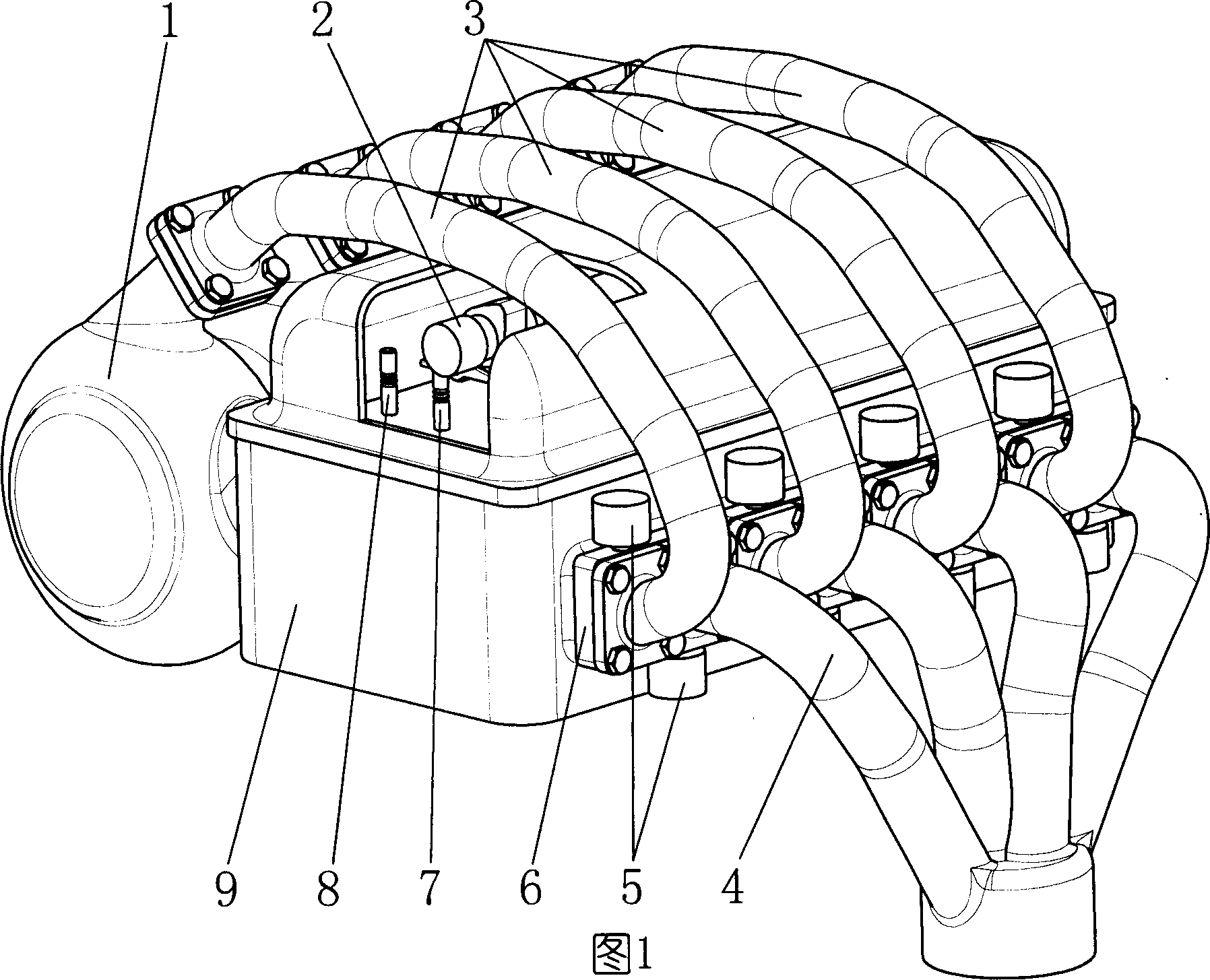
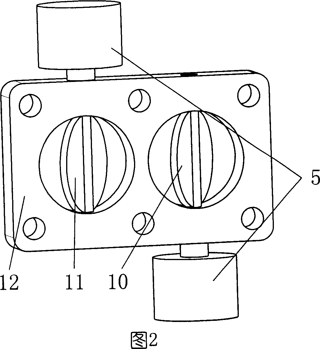
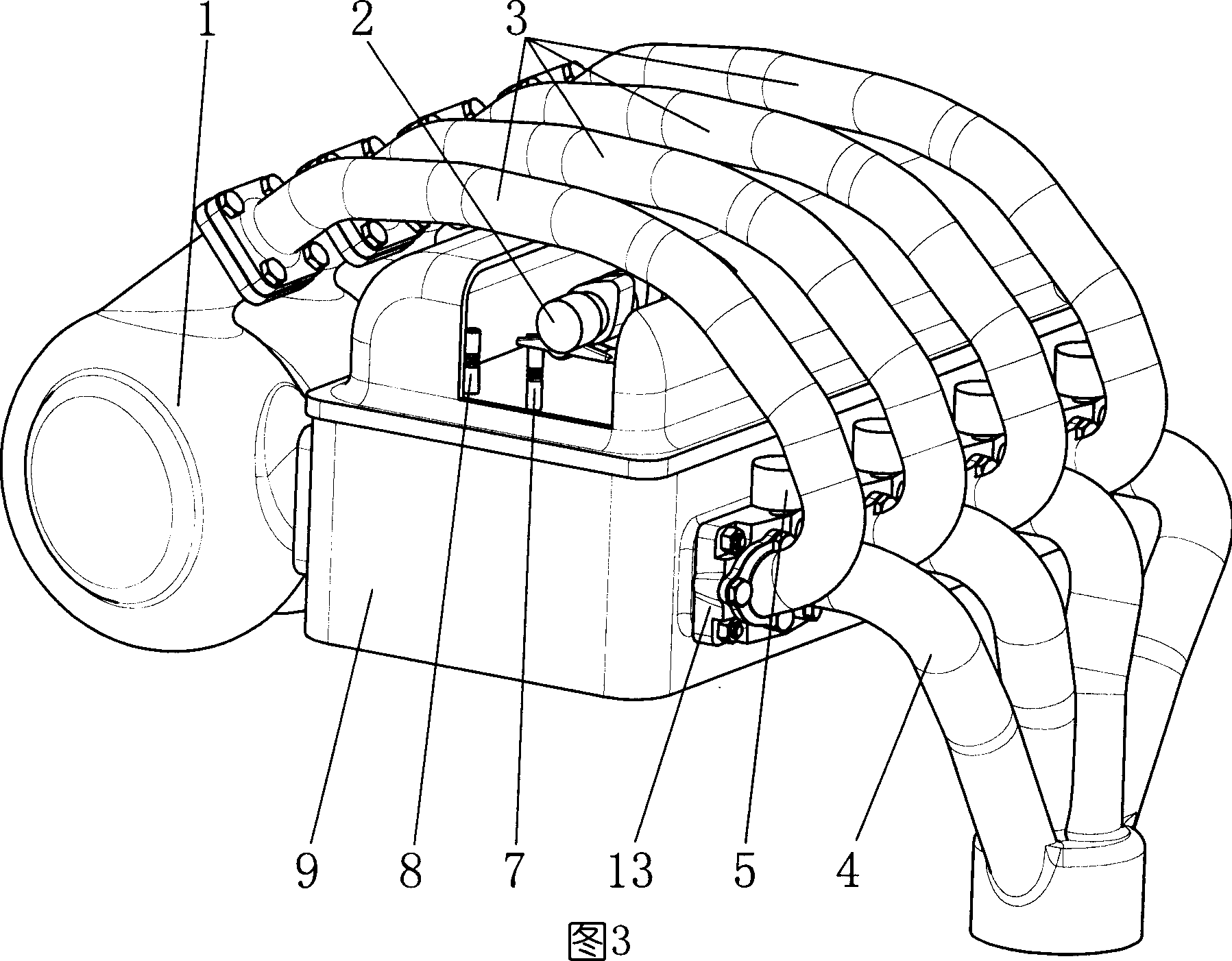
[0012] In the first embodiment shown in Figure 1, the intake valve (8) and the exhaust valve (7) are installed in the intake and exhaust passages of the engine cylinder head (9) respectively, and the camshaft (2) is installed in the intake and exhaust valves. Above, the outlets of the cylinder head intake and exhaust ducts are distributed on both sides of the cylinder head, and the intake duct (1) is installed outside the intake duct, which is connected with the cylinder head intake duct, and the control valve assembly (6) is installed outside the cylinder head exhaust duct. The exhaust pipe (4) is installed outside the control valve assembly (6), and is connected with the exhaust channel of the control valve assembly (6), and one end of the intake branch pipe (3) is installed outside the control valve assembly (6). And be connected with the intake passage of control valve assembly (6), the other end is connected with intake pipe (1), because the temperature of exhaust is very ...


PUM


Abstract

This invention relates to motor compound gas-in system, wherein, the gas cylinder channel is fixed with gas-in tube and control valve bus connected with discharge tube and with discharge channel; the control valve bus gas-in channel is connected to gas-in tube; the control valve bus discharge channel is fixed with one gas control valve and discharge control valve through screw tube to control switch between discharge tube and channel; at end of motor discharge, discharge door and control valve closes and the gas-in door opens.

Description

Technical field [0001] The invention relates to an engine composite intake system, which can significantly improve the charging efficiency of the engine, enable the engine to be filled with more charge under the same conditions, and improve the power performance, economy and emission level of the engine. Background technique [0002] At present, the intake and exhaust system of a naturally aspirated engine for automobiles is usually mainly composed of an intake pipe, an exhaust pipe, a cylinder head, an intake valve, an exhaust valve and a camshaft. When the engine is working, the intake valve opens during the intake stroke, and a certain degree of vacuum is generated in the cylinder due to the movement of the piston. And after the power stroke, the exhaust valve is opened, and the exhaust gas is discharged through the cylinder head exhaust port and exhaust pipe through the movement of the piston. Since the speed of the automobile engine is usually several thousand revoluti...

Claims


Application Information

Patent Timeline
Patent Type & Authority Applications(China)
IPC IPC(8): F02D9/00F02D9/08
Inventor 姬腾飞
Owner 姬腾飞
Learn More