Laser measuring method for non-contact type micro-rotor vibration displacement

A technology of rotor vibration and laser measurement, which is applied in the field of micro-electromechanical systems, achieves the effects of simple implementation, high measurement accuracy, and avoiding low accuracy

Inactive Publication Date: 2007-03-07
SHANGHAI JIAO TONG UNIV
View PDF0 Cites 18 Cited by
  • Summary
  • Abstract
  • Description
  • Claims
  • Application Information

AI Technical Summary

Problems solved by technology

[0003] After searching the literature of the prior art, it is found that since W.S. Bornell, G.E. Smith and others of Bell Laboratories in the United States proposed the new concept of charge coupling in 1969, with the development of science and technology, especially the development of modern electronic technology , charge-coupled device, referred to as CCD, applied to geometric measurement can achieve high precision, high efficiency, automation, dynamic detection, non-contact measurement and other requirements, especially for small size measurement has a strong advantage, S.H.Wang et al. in "Optik "A genetic optical interferometric inspection on micro-deformation" published on "(Optics) (2004, 115(12): 564-568), in which the CCD method was proposed to measure the simple microstructure of MEMS The vibration deformation and dynamic characteristics of (micro-beams and micro-films) can be measured in the range of about 1 μm, but so far, through a large number of literature searches, no method has been found to measure the vibration and dynamic characteristics of MEMS micro-rotors using CCD displacement sensing technology. any reports

Method used


Image

  • Laser measuring method for non-contact type micro-rotor vibration displacement
  • Laser measuring method for non-contact type micro-rotor vibration displacement
  • Laser measuring method for non-contact type micro-rotor vibration displacement

Examples


Embodiment 1

[0020] Select a 6mm electromagnetic thin-film micro-motor, its main technical parameters are: the diameter of the micro-rotor disk is D=6mm, the thickness of the disk is t=1.2mm, the shaft length is L=3mm, the shaft diameter is d=1.5mm, the working voltage 10V ~ 13V. The sampling frequency is 60Hz.

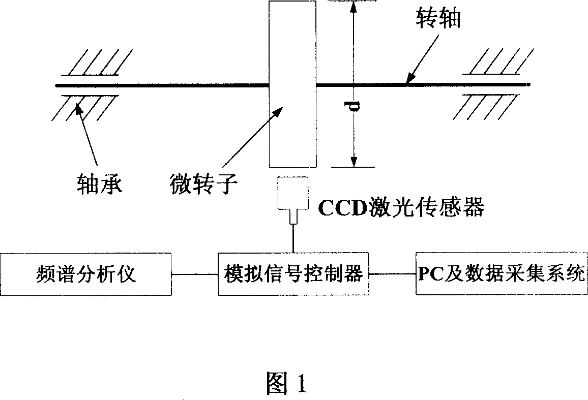
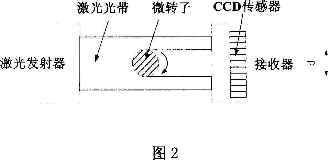
[0021] In this embodiment, in order to achieve speed control and improve positioning accuracy, a constant current subdivision drive circuit system is used to control the excitation current in the stator winding of the micro-motor, and to synthesize a magnetic field vector with constant amplitude and uniform angle change, so that the micro-motor runs smoothly ; Using CCD scanning imaging technology to sample and analyze the vibration process of the micro-rotor under the condition of controllable speed, the displacement sensor in the CCD scanning system obtains the image signal of the micro-rotor, stores it in the buffer of the signal acquisition card, and then controls it by the an...

Embodiment 2

[0024] Select a 2mm electromagnetic thin-film micro-motor, its main technical parameters are: the overall size is 2.3mm×2.3mm×1.5mm, the diameter of the micro-rotor is D=2mm, the working voltage is 8V, the working current is 70mA, and the maximum no-load speed is 25000rpm , the weight is 38mg, the speed range is 50:1, the maximum output torque is 2.8μN·m, and the rotor system adopts double-stator-single-rotor sandwich structure. The sampling frequency is 60Hz.

[0025]In this embodiment, in order to control the speed of the micro-rotor and improve the positioning accuracy, a constant current subdivision drive circuit system is used to control the excitation current in the stator winding of the micro-motor, and to synthesize a magnetic field vector with constant amplitude and uniform angle change, so that the micro-motor The operation is stable; CCD scanning imaging technology is used to sample and analyze the vibration process of the micro-rotor under the condition of controll...


PUM


Abstract

This invention relates to non-contact micro rotor vibration displacement laser measurement in the micro machine technique field. This invention uses radio ejector to send laser band to scan the micro rotor movement status, wherein, the micro rotor high speed track is collected by CCD displacement sensor and image collector card to get the vibration signals by image process technique. The invention adopts hardware system in charge for micro rotor high speed rotation to realize stable control and vibration image signal collection ad adopts software system to process the image signals to extract characteristic points to get the movement track from the fix points of rotor.

Description

technical field [0001] The invention relates to a method in the field of micro-electromechanical technology, in particular to a non-contact laser measurement method for vibration displacement of a micro-rotor. Background technique [0002] With the increasing development of science and technology, higher and higher requirements are put forward for the operating speed and working life of the micro-rotary machinery. Vibration affects the stable operation of the system. Effective and timely measurement and analysis of various vibrations has become an important link to improve the normal operation of the micro rotating machinery system. A high-precision displacement measurement system is the basis for obtaining positional accuracy in the fields of micro-machinery, instrumentation, etc., and it is also a constraint factor for the continuous progress of the above-mentioned products and technologies. At present, there are many researches on the sensing and measurement technology o...

Claims


Application Information

Patent Timeline
Patent Type & Authority Applications(China)
IPC IPC(8): G01M7/02G01B21/02
Inventor 张文明孟光李鸿光陈迪周健斌
Owner SHANGHAI JIAO TONG UNIV
Why Eureka
Try Eureka