Method for depositing metal interlaminar oxide

A deposition method and oxide technology, applied in electrical components, semiconductor/solid-state device manufacturing, circuits, etc., can solve problems such as damage to the top of the aluminum wire side, leakage of aluminum wire, etc.

Inactive Publication Date: 2007-03-07
SHANGHAI HUA HONG NEC ELECTRONICS
View PDF0 Cites 0 Cited by
  • Summary
  • Abstract
  • Description
  • Claims
  • Application Information

AI Technical Summary

Problems solved by technology

[0003] When the two-step growth method implements high-density plasma deposition, due to the plasma bombardment may cause damage to the top of the aluminum line side, the titanium nitride / titanium (TiN / Ti) film on the top layer of the aluminum line is sputtered on the bottom silicon dioxide. , resulting in possible leakage between the aluminum wires

Method used


Image

  • Method for depositing metal interlaminar oxide
  • Method for depositing metal interlaminar oxide
  • Method for depositing metal interlaminar oxide

Examples


Embodiment Construction

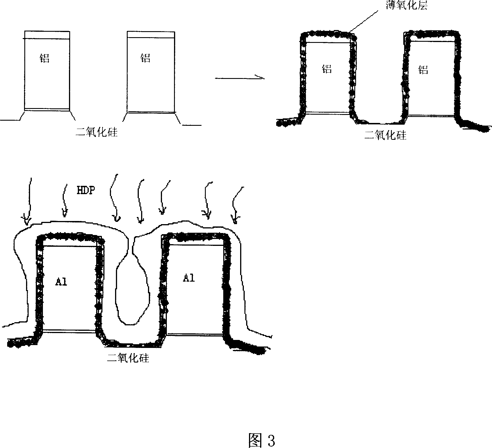
[0012] As shown in Figure 3, the intermetallic oxide deposition method of the present invention is, at first generates a thin oxide layer with chemical vapor deposition, then carries out high-density plasma deposition, and finally carries out plasma-enhanced tetraethyl silicate deposition product. Since the thin oxide layer is formed by chemical vapor deposition and can grow uniformly along the metal interface, it can well cover the protection metal line.

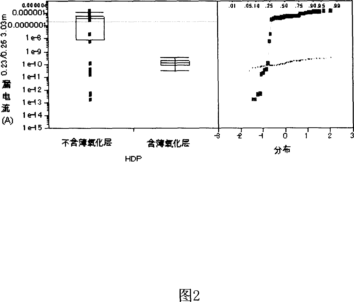
[0013] Figure 2 is the test data of two groups of control leakage current experiments, one group has a thin oxide layer, and the other group has no thin oxide layer. It can be seen from the figure that with the addition of a thin oxide layer, the leakage current distribution is dense and all less than 1E-9A, while the leakage current distribution of a group without a thin oxide layer is discrete, most of which are greater than 1E-7A. So increasing the thin oxide layer can significantly reduce the leakage current.

[0014]...


PUM


Abstract

This invention discloses one metal oxidation deposition method, which introduces chemical gas deposition before high intensity plasma to generate one film of oxidation layer to block damage on the alumina line by plasma. The invention can effectively reduce IMD deposition damage and leakage current.

Description

technical field [0001] The invention relates to a manufacturing process method of a semiconductor integrated circuit, in particular to a metal interlayer oxide deposition method. Background technique [0002] The existing intermetal oxide deposition (IMD) is generally divided into two steps (the cross-sectional schematic diagram is shown in Figure 1): firstly, high-density plasma deposition (HDP) is performed, and in this step, while the oxide film is growing, another The purpose of plasma bombardment is to allow silicon oxide to fill up the dense aluminum wires without leaving gaps. Plasma-enhanced tetraethyl silicate (PE-TEOS) deposition is then performed, which is the main oxide film growth step. [0003] When the two-step growth method implements high-density plasma deposition, due to the plasma bombardment may cause damage to the top of the aluminum line side, the titanium nitride / titanium (TiN / Ti) film on the top layer of the aluminum line is sputtered on the bottom s...

Claims


Application Information

Patent Timeline
IPC IPC(8): H01L21/31
Inventor 罗来青
Owner SHANGHAI HUA HONG NEC ELECTRONICS
Why Eureka
Try Eureka