

Low-temperature high agent-oil ratio catalytic conversion reaction method and reactor
A catalytic conversion and reactor technology, which is applied in catalytic cracking, cracking, petroleum industry, etc., can solve problems affecting economic benefits, etc., and achieve the effects of optimizing reaction conditions, being easy to use, and inhibiting thermal cracking reactions
Inactive Publication Date: 2007-03-14
石宝珍
View PDF6 Cites 8 Cited by
- Summary
- Abstract
- Description
- Claims
- Application Information
AI Technical Summary
Problems solved by technology
As a result, excessive thermal cracking reactions occur, and too much raw material oil is converted into by-products such as dry gas and coke, which affects economic benefits
Method used
View moreImage
Smart ImageViewing Examples

Examples
Embodiment 2
[0030] Example 2. On the basis of Example 1, the catalyst reflux rate to the second reaction zone was increased to 300t / h. At this time, the catalyst circulation in the high-speed reaction zone is 1430t / h, and the catalyst circulation in the low-speed reaction zone is 1730t / h. Other parameters are the same as Example 1.
[0031] The comparative example is the same as Example 1. The comparison results are given in Table 2.
[0032] project
[0033] project
Login to View More PUM
 Abstract
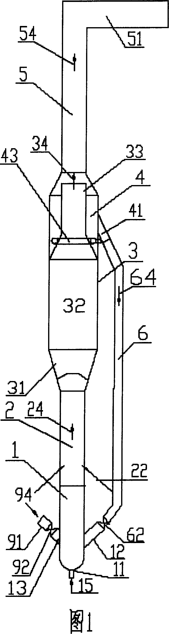
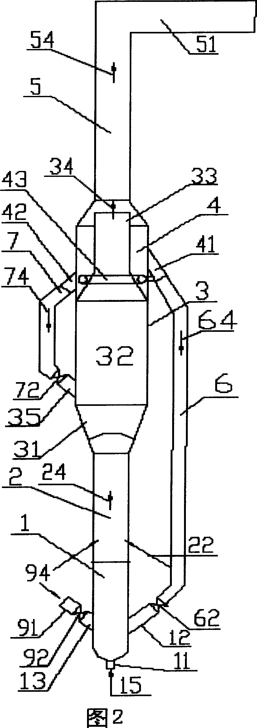
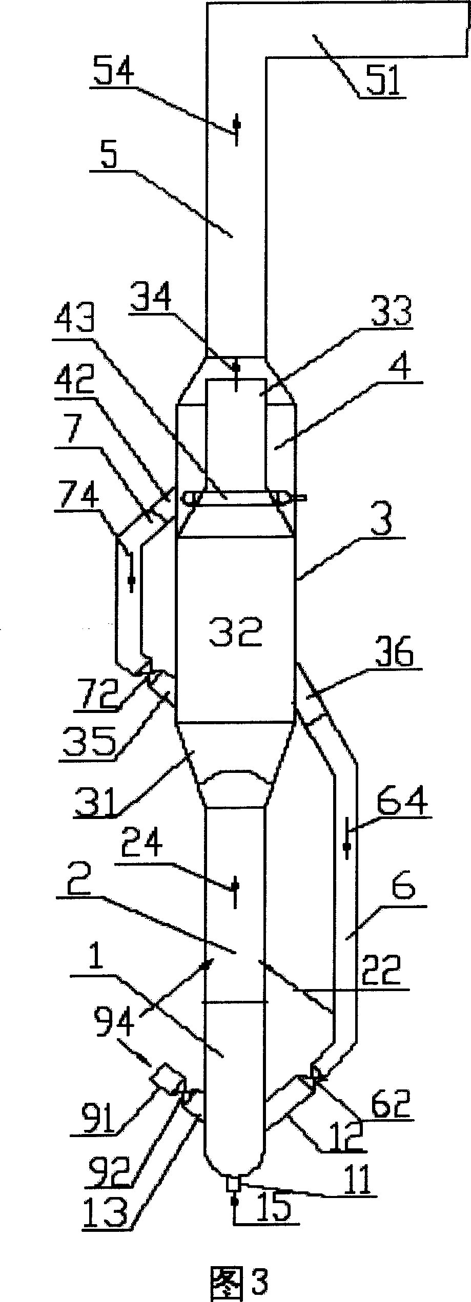
The present invention provides catalytic reaction method and reactor capable of improving reaction condition and raising the product yield. The present invention features that catalyst is made to reflux in the reactor and this can lower the temperature of catalyst contacting with reacted material, increase the practical catalyst amount, inhibit thermal cracking reaction, raise product yield, raise the catalyst inventory and catalyst / oil ratio in the second reaction region, improve product distribution and raise product quality. The reactor of the present invention features its catalyst reflux without affecting the operation of the other parts and without needing improving or increasing depositor. The present invention can raise product yield and lower the olefin content in gasoline product.
Description
technical field [0001] The invention belongs to the technical field of petroleum catalytic conversion devices, and in particular relates to a method and a riser reactor which can be used for catalytic conversion of petroleum hydrocarbon raw materials. Background technique [0002] Almost all existing catalytic conversion devices for petroleum hydrocarbon raw materials (including atmospheric heavy oil, vacuum oil press, vacuum wax oil, coker wax oil, gasoline, etc.) use riser reactors, and the reaction raw materials are catalytically converted in the riser reactor to form Gasoline, diesel, liquefied petroleum gas and other reaction products. [0003] With the deepening and popularization of research work, the catalytic conversion reaction process and equipment have been continuously improved. Advances in reaction engineering can be divided into two aspects: the associated conditions and the reaction process itself. In the field of related conditions, a variety of more effic...
Claims
Login to View More Application Information
Patent Timeline
 Patent Type & AuthorityApplications(China)
IPC IPC(8): C10G11/00
Inventor石宝珍
Owner石宝珍