
Pretreating equipment for improving yarn sizing performance
A pretreatment and equipment technology, applied in the direction of ultrasonic/sonic fiber treatment, etc., can solve problems such as refractory degradation, deterioration of water solubility, and environmental impact
- Summary
- Abstract
- Description
- Claims
- Application Information
AI Technical Summary
Problems solved by technology
Method used
Image

Examples
Embodiment Construction
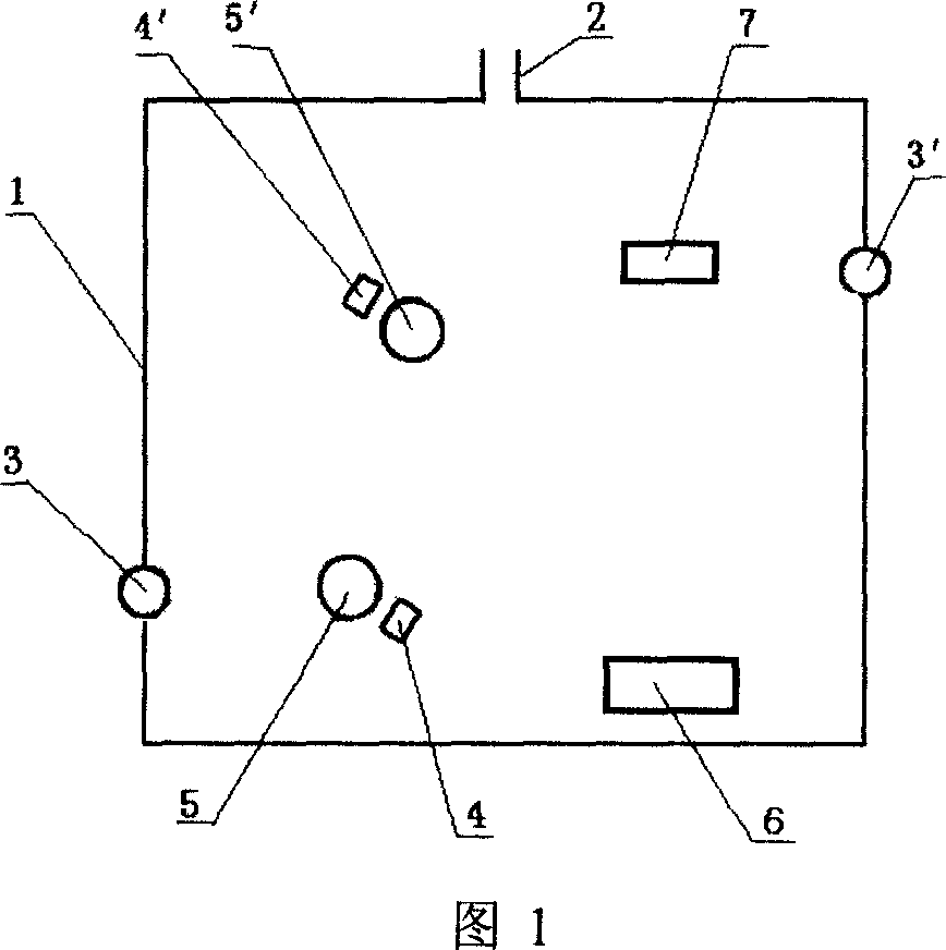
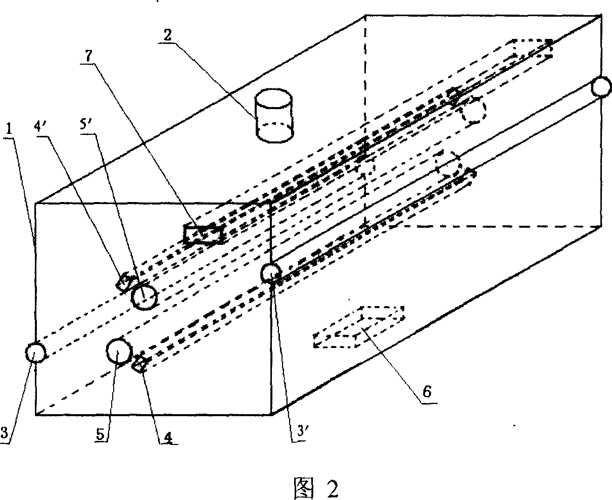
[0010] The pretreatment equipment and treatment process of the present invention will be described in detail below in conjunction with the accompanying drawings.
[0011] See accompanying drawing 1, accompanying drawing 2.
[0012] The pretreatment equipment of the present invention is composed of a box body 1, guide rollers 5, 5', high-voltage discharge heads 4, 4', ozone generator 6, ultraviolet irradiation device 7 and sealing rubber rollers 3, 3'.
[0013] Sealing rubber rollers 3, 3' are respectively fixedly installed on the two opposite walls of the box body 1, and the two ends of the guide rollers 5, 5' installed in the box body are respectively fixedly installed on the two side walls of the box body 1, from The yarn drawn on the warping beam advances along the route formed by the rubber seal roller 3, the guide roller 5, the guide roller 5' and the rubber seal roller 3'.
[0014] The high-voltage discharge heads 4, 4' fixedly installed in the box body 1 are respective...
PUM
 Abstract
Description
Claims
Application Information