Measuring system and screening method for thermal conductivity assembly heat conductivity

A technology of thermal conductivity and measurement system, which is applied in the direction of semiconductor devices, semiconductor/solid-state device parts, electrical components, etc., can solve the problem of low reference value, high manpower and time cost, measurement value reproducibility, resolution and reliability Stability and other issues to achieve stable reproducibility, reduce manpower and time costs, and shorten the measurement time

A technology of thermal conductivity and measurement system, which is applied in the direction of semiconductor devices, semiconductor/solid-state device parts, electrical components, etc., can solve the problem of low reference value, high manpower and time cost, measurement value reproducibility, resolution and reliability Stability and other issues to achieve stable reproducibility, reduce manpower and time costs, and shorten the measurement time

CN1932494AActive Publication Date: 2007-03-21YEH CHIANG TECH CORP

Image

  • Measuring system and screening method for thermal conductivity assembly heat conductivity
  • Measuring system and screening method for thermal conductivity assembly heat conductivity
  • Measuring system and screening method for thermal conductivity assembly heat conductivity

Examples


Embodiment Construction

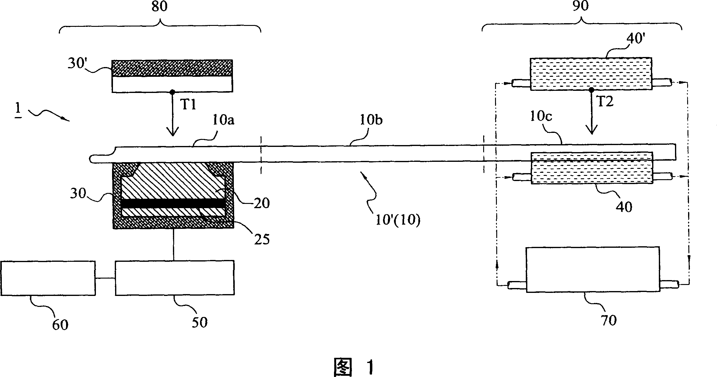
[0023] The measurement system and screening method for the thermal conductivity of thermal conduction components of the present invention are applied to quickly measure the thermal conductivity of thermal conduction components such as heat pipes, vapor chambers, heat sinks, etc., such as: temperature difference Ξ”T, contact thermal resistance R and maximum Heat transfer Qmax, etc., in order to achieve the purpose of rapid quantification and screening. The following embodiment will further illustrate the technical characteristics of the present invention by taking the heat pipe 10' as the representative object to be tested. This embodiment is only a preferred example and is not used to limit the scope of the present invention. Please refer to the accompanying drawings in conjunction with the following Explain in detail for best understanding.

[0024] First, please refer to FIG. 1, which is a schematic diagram of a measurement system 1 for the thermal conductivity of the thermal...


PUM


Abstract

A measuring system for the temperature conductivity of the thermal conducting module is to set the heated metal mass temperature of the heating end and the radiating water cover temperature of the radiating end. So it can generate the temperature difference between the heating end and the thermal conducting module to compare the cooling speed of the heating metal mass to determine the temperature conductivity. In addition, it can get the relative performance number by the heat changing in the cooling process to get the Qmax value by conversing with the biggest performance number. Also the invention provides a method to select the temperature conductivity of the thermal conducting module by defining the cooling curve of the standard sample.

Description

technical field [0001] The present invention relates to a measurement system and screening method for the thermal conductivity of thermal conductivity components, in particular to a method for quickly measuring the thermal conductivity of thermal conductivity components to achieve the purpose of screening the thermal conductivity of thermal conductivity components, which can greatly reduce manpower and time Cost, and has stable reproducibility, high resolution and reliability. Background technique [0002] With the trend of miniaturization and multi-functionalization of electronic products, it is accompanied by the impact on components and systems. Because more transistors need to be accommodated in a limited space, more heat will be generated and the performance of electronic components will be unstable, which is a great challenge for engineers in related fields. The current traditional system heat dissipation solution is mainly to guide the heat generated by high heat gen...

Claims


Application Information

Patent Timeline
21 Mar 2007
Publication
CN1932494A
IPC
G01N25/20; H01L23/36
Inventors
ζŽε…‹ε‹€; ζž—ζŒ―ε·