Sun's rays generating device

A technology of power generation device and sunlight, applied in the direction of photovoltaic power generation, optical radiation generator, generator/motor, etc., can solve many problems such as extremely high power, difficulty and unavoidable, and prevent the temperature rise and prolongation of some parts. effect of life

Inactive Publication Date: 2007-03-21
武藤健一
View PDF4 Cites 98 Cited by
  • Summary
  • Abstract
  • Description
  • Claims
  • Application Information

AI Technical Summary

Problems solved by technology

[0022] The present inventors have found that when two solar cell modules shown in FIG. 7 are connected in series, when a current difference (difference in light intensity) occurs in each current source, the current in the solar cell module with the smaller current does not stop, and flows to For the bypass diode Db set for each solar cell module, this causes a significant double peak in the output characteristics
In addition, when two of the above-mentioned solar cell modules are connected in parallel, the voltage difference between each module due to the temperature difference between the two also shows a double peak. The cause was found to be the influence of the reverse current prevention diode Da
[0023] Therefore, in the case of a solar cell array formed by connecting multiple solar cell modules in series and parallel, due to the influence of the current and voltage changes of each module, there may be multiple maximum power points.
[0024] The research of the present inventor shows that, in the traditional solar power generation device (system) that double-peak property inevitably occurs u

Method used


Image

  • Sun's rays generating device
  • Sun's rays generating device
  • Sun's rays generating device

Examples


Embodiment Construction

[0094]Embodiments of the photovoltaic power generation device of the present invention will be described with reference to the drawings.

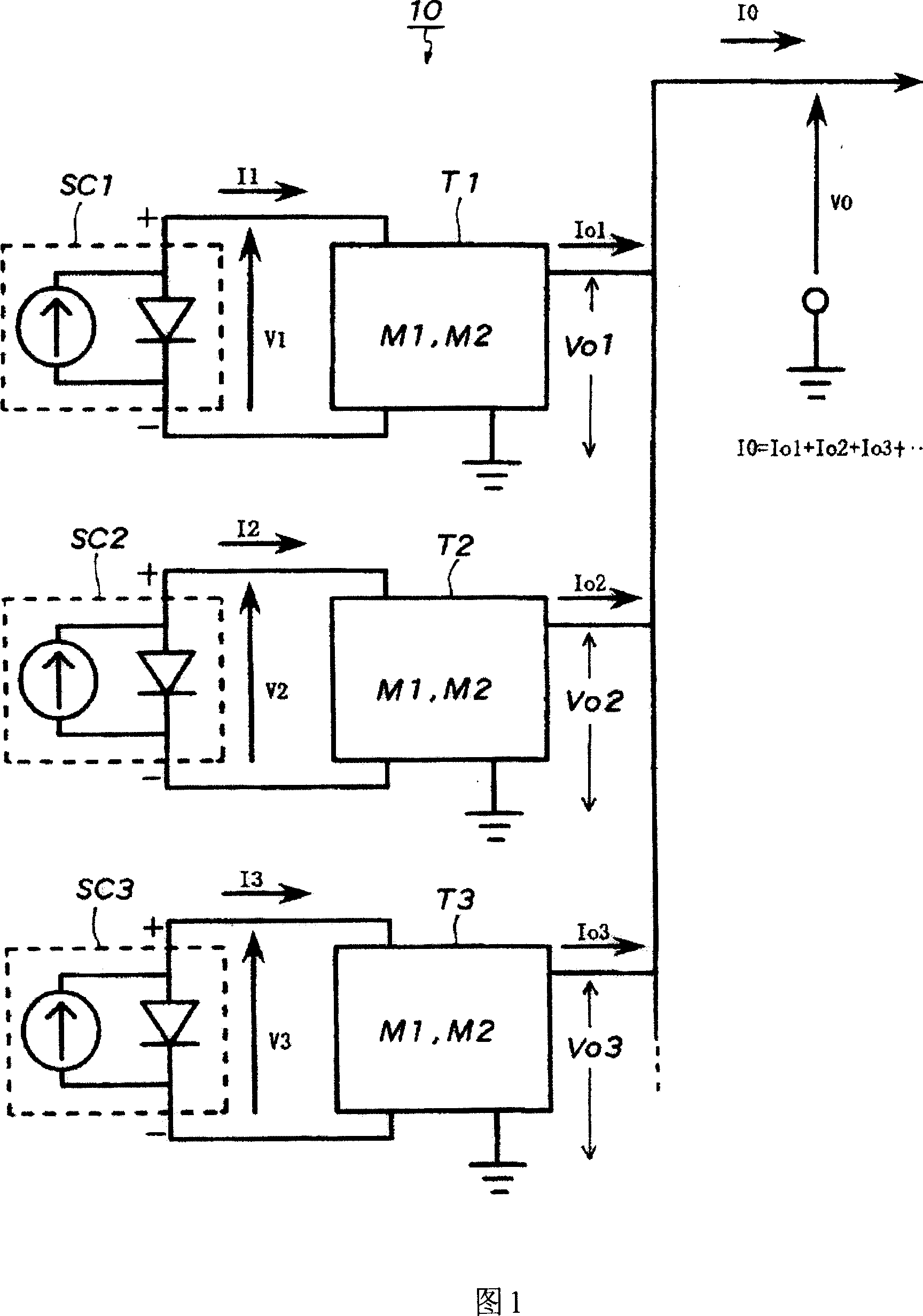
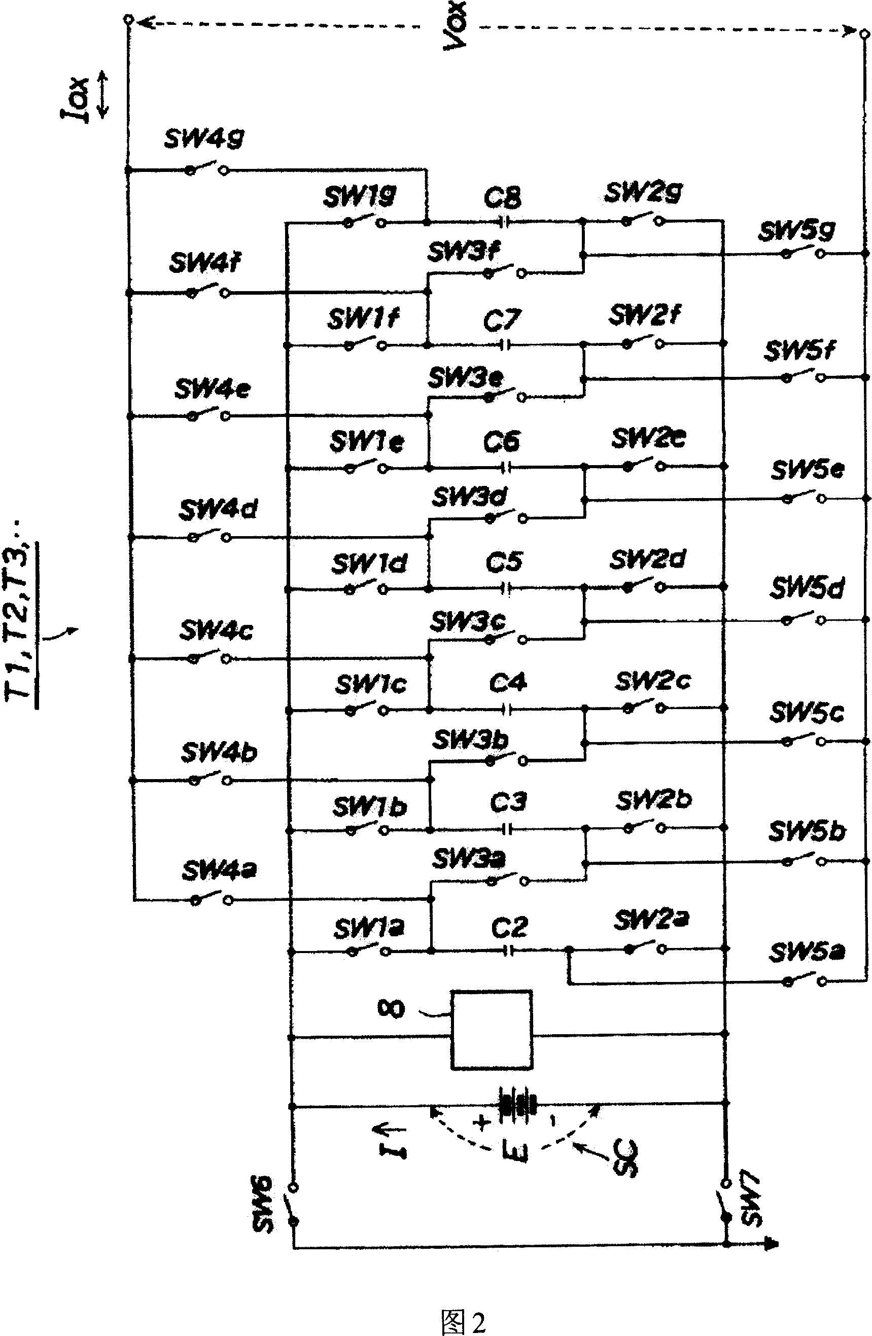
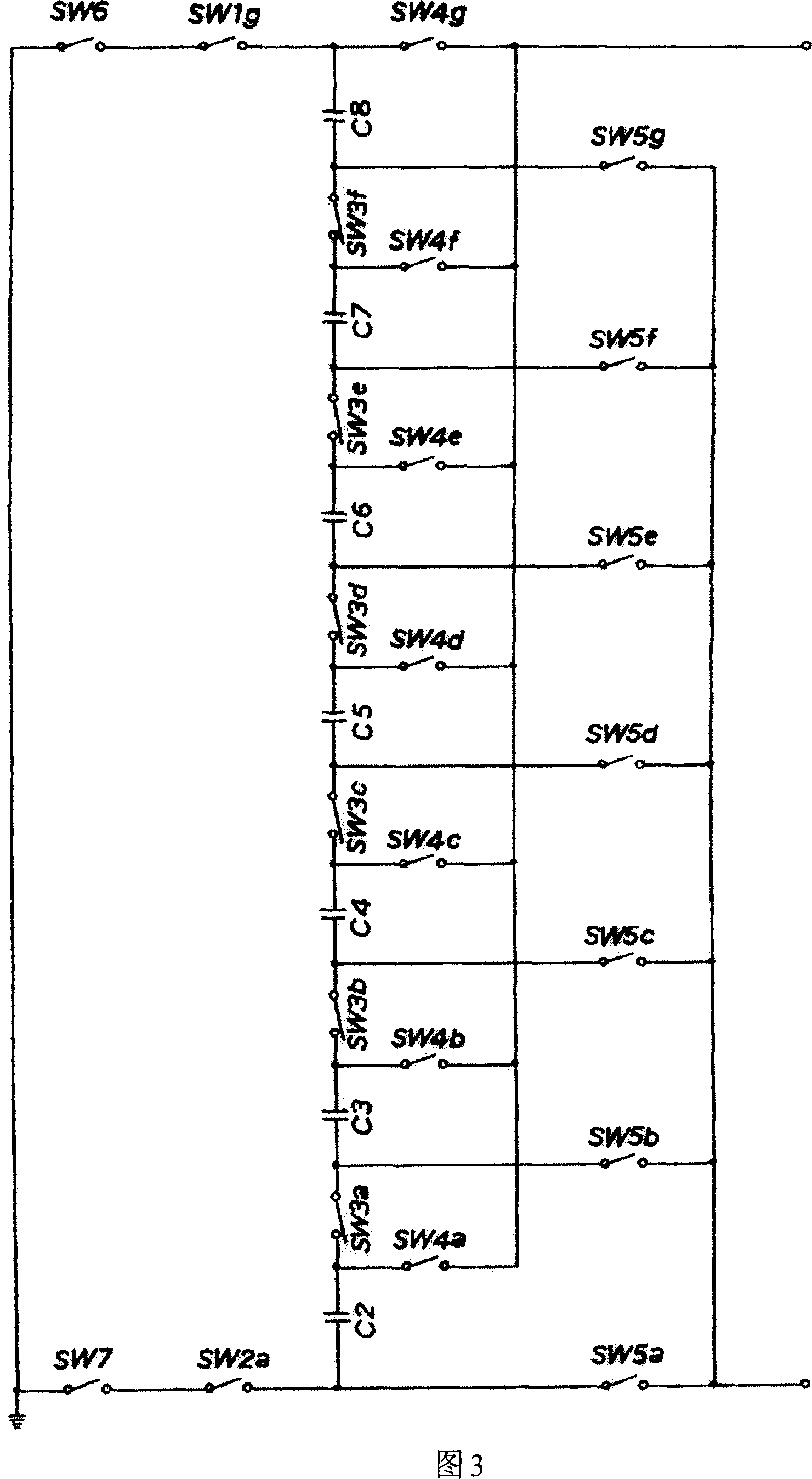
[0095] FIG. 1 is a block diagram of a photovoltaic power generation device according to a first embodiment of the present invention. 2 is a circuit diagram of a preferred example of a charge transfer circuit provided in each solar cell body of the photovoltaic power generation device according to the first embodiment of the present invention. FIG. 3 is a circuit diagram showing the connection state of the circuit at the output of the above-mentioned charge transfer circuit. 4 is a schematic diagram of the amount of transferred charge per switching cycle, which is the output current corresponding to the voltage change of the connected system (AC power supply) available at the output of the charge transfer circuit. Fig. 5 is a block diagram of a photovoltaic power generation device according to a second embodiment of the present invention. ...


PUM


Abstract

The invention discloses a photovoltaic power generator capable of obtaining electric power from a solar cell at the maximum efficiency all the time, even under an uneven sunshine condition. The photovoltaic power generator 10 includes: a plurality of solar cell bodies SC1, SC2, ... formed by connecting the solar cells in series or in series-parallel connection; and a plurality of charge transfer circuits T1, T2, ... which are set for each solar cell body one by one and whose input terminals are connected with the anode and cathode of each solar cell body and output terminals are connected with a loading side in parallel. Each charge transfer circuit comprises: a plurality of capacitors C2-C8 which cumulate the output of the solar cell bodies in a form of charges; a plurality of semiconductor switching member SW1a~, SW2a~, SW3a~, SW4a~, SW5a~, SW6, SW7; a tracking control member M1 for a maximal power of the solar cell bodies; and an output controlling member M2 for transferring the charges cumulated in the capacitors to the loading side, so as to enable the output voltage Vox to be tracked approximately equal to a terminal voltage Vo of the loading side.

Description

technical field [0001] The present invention relates to a photovoltaic power generation device that efficiently obtains power from a solar cell, charges a secondary battery, and is used in connection with a power system. Background technique [0002] A solar cell element (battery) is the smallest unit of power generation represented by an equivalent circuit of a current source and a diode (solar cell body), and its output density is small. Usually, a structure formed by connecting multiple solar elements in series or in parallel basic unit. [0003] In practice, for example, the equivalent circuit shown in Fig. 7 adopts a solar cell body SC connected in series by multiple solar cell elements (Fig. 7 is an example of seven solar cell elements connected in series, represented by a current source and seven series diodes. ) and a solar cell module in which a bypass diode Db and a backflow prevention diode Da are connected to prevent elements that do not generate electricity. ...

Claims


Application Information

Patent Timeline
IPC IPC(8): H02N6/00H02J15/00H02S40/38
CPCY02E70/30Y02E10/50
Inventor 武藤健一
Owner 武藤健一
Why Eureka
Try Eureka