Carbon-fiber composite material high-speed air-craft rectifying cover surface transient temperature measuring apparatus

A technology of high-speed aircraft and composite materials, which is applied in the field of measuring the transient temperature of the fairing surface of carbon fiber composite high-speed aircraft, which can solve the problems of large difference in thermal expansion coefficient, high price, and inaccurate surface temperature measurement, etc., to eliminate temperature measurement Hysteresis, the effect of accurate test results

Inactive Publication Date: 2007-03-28
BEIHANG UNIV
View PDF0 Cites 16 Cited by
  • Summary
  • Abstract
  • Description
  • Claims
  • Application Information

AI Technical Summary

Problems solved by technology

The traditional method is to bond the temperature measuring thermocouple on the surface of the non-metallic material shell. Since the adhesive layer covers the front temperature sensing part of the temperature measuring thermocouple, and the adhesive layer has a certain thickness, it affects the heat conduction speed. The temperature measuring thermocouple cannot immediately respond to the rapid change of the shell surface temperature
In addition, the thermal expansion coefficients of the temperature sensor made of metal materials and the carbon fiber composite shell of non-metal materials are very different. The situation where the temperature sensor is debonded and separated from the non-metallic carbon fiber composite shell, resulting in inaccurate surface temperature measurement
Carbon fiber composite high-speed aircraft fairings are very expensive. Due to thermal ablation, multiple high-temperature tests cannot be repeated on the same high-speed aircraft fairing. The test data obtained from each test is extremely valuable

Method used


Image

  • Carbon-fiber composite material high-speed air-craft rectifying cover surface transient temperature measuring apparatus
  • Carbon-fiber composite material high-speed air-craft rectifying cover surface transient temperature measuring apparatus

Examples


Embodiment Construction

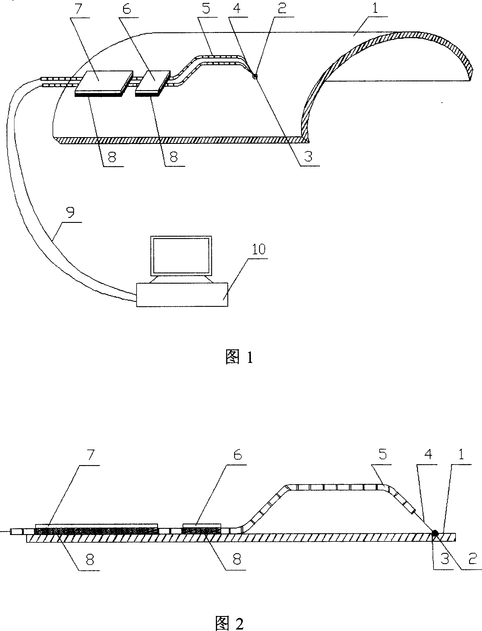
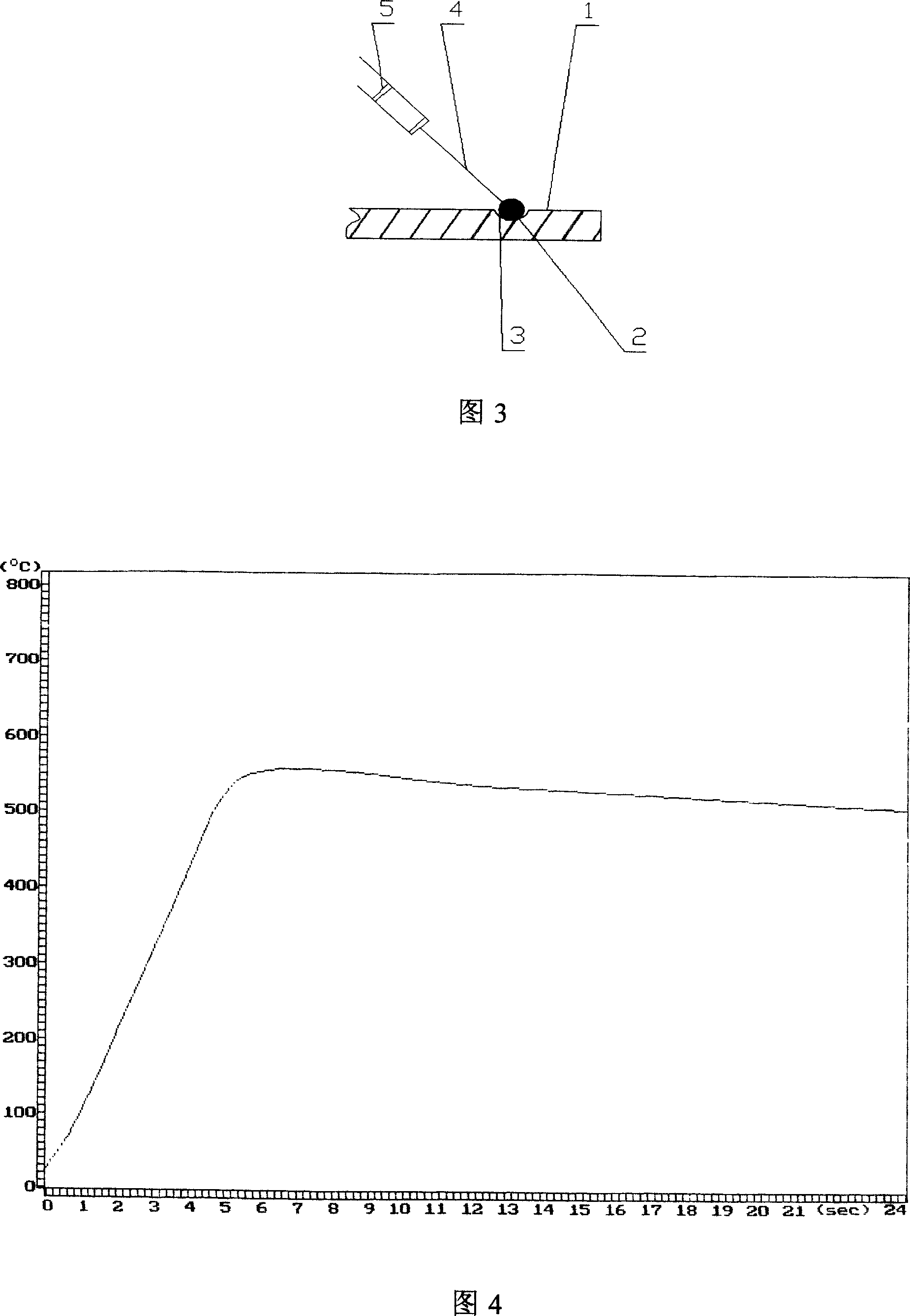
[0015] As shown in Fig. 1, Fig. 2 and Fig. 3, the present invention is made up of thermocouple 4 for temperature measurement, ceramic insulating tube 5, stainless steel pressing piece 6 and 7 and computer 10, and the front part of thermocouple 4 is bent into a bow shape, and the front end of thermocouple Put the bead-shaped temperature-sensing part 2 into the shallow semicircular groove 3 on the surface 1 of the carbon fiber composite high-speed aircraft, press a piece of stainless steel sheet 7 slightly far from the front end of the thermocouple against the thermocouple, and fix it with high-temperature glue 8 On the surface of the projectile body, press and fix it with a heavy object when bonding. After the bonding high-temperature adhesive is completely cured and hardened, press and bond the second piece of stainless steel pressure piece 6 that is slightly closer to the front end of the thermocouple to make it press At the bow-shaped root of the front end of the thermocouple...


PUM


Abstract

This invention relates to a temperature-test device for surface instant temperature of a commutation cover of a carbon fiber compound material high speed aerocaft including a thermocouple, two press plates and a computer, in which, the front of the thermocouple is welded to a bead, a shallow half round groove is processed on the surface of the aerocaft, the front bead temperature-sensing part of the thermocouple is put in the groove and the front of its wire is bended to an arch to drive two separated press-plates to press the front of the thermocouple to let the temperature-sensing part keep a downward pressure in the experiment to secure it to be contacted with the surface of the aerocaft closely, and the output of the thermocouple is transmitted to the computer via a lead to compute the instant temperature variance curve of the surface of the aerocaft in the process of hot impact experiment.

Description

technical field [0001] The invention relates to the measurement of the transient temperature on the surface of the fairing of a high-speed aircraft made of carbon fiber composite material, especially when the surface of the fairing of a high-speed aircraft is in a state of high-speed thermal shock during a simulated supersonic flight test, the temperature of the surface of the fairing made of a carbon fiber composite material at the front end of the high-speed aircraft is Dynamic high temperature changes for transient testing. Background technique [0002] When the aircraft is flying at high speed, the dynamic variation of the surface temperature of the front end shell is a key parameter to study whether the shell material can resist the high temperature transient thermal shock during high-speed flight. Measured and recorded in the high-speed thermal flow field, the surface temperature of the aircraft The work on the transient process has very important practical significanc...

Claims


Application Information

Patent Timeline
IPC IPC(8): G01K1/14G01K7/02G01K3/08G01K1/022G01K1/143
Inventor 吴大方杨嘉陵高镇同晏震乾赵寿根
Owner BEIHANG UNIV
Why Eureka
Try Eureka